| IEC60092 Offshore & Marine Cables | |||
| MariTox Marine Flame Retardant Medium Voltage Cables | MariTox Marine Flame Retardant Power & Control Cables | MariFlex Marine Fire Resistant Power & Control Cables | other |
 Water Blocked
S10 IYOI(c) 60 V
Applications
S10 IYOI(c) 60 V Marine cables are flame retardant, low smoke and halogen free, used for indoor
telecommunication.
Standards
IEC 60092-360
IEC 60332-1
IEC 60332-3-22
IEC 60754-1,2
IEC 61034-1,2
NEK 606
VG 95218 part 29

-
Construction
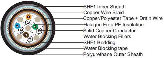
Conductors: Solid tinned copper, 0.5mm.
Insulation: Halogen-free thermoplastic compound PE.
Twinning: Colour coded cores twisted together. Pairs are cross-stranded to finished cable or 10 pair units. The
units are stranded to 20 - 30 - 50 pair cables. 2 pair is stranded as a star quad.
Filler: Water blocking fillers, if required.
Wrapping: Polyester tape.
Collective Shielding: The cable core is screened by copper backed polyester tape in contact with a 0.5mm solid
tinned drain wire.
-
Bedding: Halogen-free thermoplastic compound, type SHF1, coloured grey, PETP wrapping tape will be applied
-
over the bedding, if required.
-
Armour: Copper wire braid, PETP wrapping tape will be applied over the braiding, if required.
-
Water Blocking Elements: Water blocking tape and strings for providing longitudinal water tightness.
-
Inner Sheath: Halogen-free thermoplastic compound, type SHF1, coloured grey.
-
Outer Sheath: Polyurethane for providing transversal water tightness, PE is optional,but can not meet low
-
smoke standard.
Electrical Characteristics
| Nominal Conductor Diameter | mm | 0.5 |
|---|---|---|
| Maximum Resistant@20℃ | Ω/km | 95 |
| Nominal Inductance@1KHz | MH/km | 0.61 |
| Mutual Capacitance 1-pair cable | nF/km | 90 |
| Mutual Capacitance 2-pair cable | nF/km | 80 |
| Mutual Capacitance 4-pair and above cable | nF/km | 70 |
| Operating Voltage | V | 60 |
Mechanical and Thermal Properties
Bending Radius : 8×OD (during installation); 6×OD (fixed installed).
Temperature Range : -10℃ ~ +60℃.
Dimensions and Weight
Construction No. of elements×No. of cores in element×Core diameter mm |
Nominal Insulation Thickness mm |
Nominal Bedding Thickness mm |
Nominal Inner Sheath Thickness mm |
Nominal Outer Sheath Thickness mm |
Nominal Overall Diameter mm |
|---|---|---|---|---|---|
| 1×2×0.5 | 0.2 | 1.2 | 1.2 | 1 | 10.0±2.0 |
| 2×2×0.5 | 0.2 | 1.2 | 1.2 | 1 | 11.0±2.0 |
| 4×2×0.5 | 0.2 | 1.2 | 1.2 | 1 | 12.0±2.0 |
| 10×2×0.5 | 0.2 | 1.5 | 1.5 | 1 | 14.0±2.0 |
| 20×2×0.5 | 0.2 | 1.5 | 1.5 | 1 | 17.0±2.0 |
Note: The parameters listed above are nominal values as per cable standards. Actual values may vary due to material and manufacturing process variations. For precise specifications or customized requirements, please contact us for further information


