Ordering Options Ordering Options
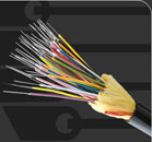
Multi Loose Tube Cable
| CCL-FC-MLA-B-C×D-E-F-G-H×I-J-K-L |
| A: Loose tube diameter |
|
| |
B=2.1mm, C=2.5mm, D=2.8mm, E=3.0mm, F=3.2mm |
| B: Fiber type |
|
| |
0=Fiber and copper conductors in cable
4=50/125 multi-mode fi ber (OM3) per ITU-T G.651
5=50/125 multi-mode fi ber (OM2) per ITU-T G.651
6=62.5/125 multi-mode fi ber (OM1) per ITU-T G.651
7=NZDS SM fi ber per ITU-T G.656.
8=NZDS SM fi ber per ITU-T G.655.
9=Standard SM fi ber per ITU-T G.652.D
Ended with R=Ribbon type fi ber ( Ex: 9R= SM fi ber per G.652.D ribbon type ) |
| C: No. of tubes: |
|
| |
1 to 36 |
| D: No. of fi bers per tubes: |
|
| |
2 to 12 |
| E: Central member |
|
| |
S=Solid steel, SR=Stranded steel, F=Fiber Reinforced Plastic (FRP) |
| F: Inner jacket options |
|
| |
2Y=PE, Y=PVC, H=LSZH |
| G: Armour options |
|
| |
Blank=No armour, T=Corrugated steel tape armour, W=Steel wire armour B=Bronze armour, D=Fiber glass armour; TW= Steel tape + Steel wire armour |
| H: Jacket material options |
|
| |
2Y=PE, Y=PVC, H=LSZH, 11Y=PU, A=Aluminium moisture barrier, T=Anti-termite protection |
| I: Water-blocking options for cable core |
|
| |
X=No water-blocking; J= Water blocking gel in tubes; JD=Water-blocking gel in tubes + dry water blocking in cable core interstices; JJ= Water-blocking gel in tubes and cable core interstices. |
| J: Water-blocking options for cables with more than one jacket |
| |
X=No water-blocking, J= Water blocking gel between jackets; D=Dry water-blocking between cable jackets; |
| K: Strength member options |
|
| |
A=Aramid yarn, AG=Aramid yarn and fi berglass yarn, G=Fiberlass yarn |
| L: General options |
|
| |
SS=Fig-8 self-supporting UW=Under Water |
ADSS Multi Loose Tube Cable
| CCL-FC-MLA-B-C-D-E-F-G-H-I-J-K-L-M- ADSS |
| A: Loose tube diameter |
|
| |
B=2.1mm, C=2.5mm, D=2.8mm, E=3.0mm, F=3.2mm |
| B: Fiber type |
|
| |
0=Fiber and copper conductors in cable
4=50/125 multi-mode fi ber(OM3)
5=50/125 multi-mode fi ber(OM2)
6=50/125 multi-mode fi ber(OM1)
7=NZDS SM fi ber per G.656.
8=NZDS SM fi ber per G.655.
9=Standard SM fi ber per G.652.D
Ended with R=Ribbon type fi ber ( Ex: 9R= SM fi ber per G.652.D ribbon type ) |
| C: No. of tubes: |
|
| |
01 to 36 |
| D: No. of fi bers per tubes: |
|
| |
02 to 12 |
| E: Central member |
|
| |
S=Solid steel, SR=Stranded steel, F=Dielectric(FRP) |
| F: Inner jacket options |
|
| |
2Y=PE, Y=PVC, H=LSZH |
| G: Armour options |
| |
T=Corrugated steel tape armour, B=Bronze, W=Steel wire Armour, WB= Steel Wire |
Braid
H: Jacket material options |
| |
2Y=PE, AT= Anti-tracking |
| I: Water-blocking options for cable core |
|
| |
X=No water-blocking; J= Water blocking gel in tubes; JD=Water-blocking gel in tubes + dry water blocking in cable core interstices; JJ= Water-blocking gel in tubes and cable core interstices. |
| J: Water-blocking options for cables with more than one jacket |
| |
X=No water-blocking, J= Water blocking gel between jackets; |
| K: Strength member options |
|
| |
A=Aramid yarn, AG=Aramid yarn and glass yarn, G=Glass yarn |
| L: Span Length |
|
| M: Voltage Rating |
|
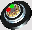
Opgw Type Cable
CCL-FC-A-B-C-D-E-OPGW |
| A: Fiber type |
|
| |
0=Fiber and copper conductors in cable
4=50/125 multi-mode fi ber(OM3)
5=50/125 multi-mode fi ber(OM2)
6=50/125 multi-mode fi ber(OM1)
7=NZDS SM fi ber per G.656.
8=NZDS SM fi ber per G.655.
9=Standard SM fi ber per G.652.D |
| B: No. of steel tubes: |
|
| |
01 to 3 |
| C: No. of fi bers per tubes: |
|
| |
02 to 12 |
| D: Cross Sectional Area |
|
| |
35=35mm2; 50=50mm2; 70=70mm2; 90=90 mm2; 130=130mm2 |
| E: Rated Voltage |
|
| |
66=66KV; 115=115kV; 150=150kV;
250=250kV; 275=275kV; 380=380kV; 500=500kV |
<<Return
|