


| Motor Connecting Cables | |||
| 2YSLCY-JB/2YSLCYK-JB | 9YSLCY-JB | 9YSLCYK-JB+3 | Insulation color code |
 2YSLCY-JB+3/2YSLCYK-JB+3
Application
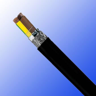
These cables are double shielded, large gauge size, PVC motor supply cables Polyethylene insulation over very
fine stranded copper provides a low-loss transfer of power, excellent low capacitance performance and superior
flexibility when compared to conventional PVC cables. The applications include frequency converters, motor runs,
connections with high electromagnetic interference. Found in the automotive, paper and food industry,
environmental technology, packaging industry, machine tools and handling equipment. The overall foil and braid
shield offer excellent protection against electromagnetic and electrical interferences. For medium mechanical
stresses found indoors in dry, moist and wet areas. For 2YSLCYK-JB ,the black UV- resistant jacket also allows
for outdoor use and for direct burial applications.
Standard
VDE 0250 & 0281, EMC to EN 55011, EMC to VDE-0875 part-11, CE Low Voltage Directive 73/23/EEC and
93/68/EEC, ROHS compliant
Cable construction

Stranded bare copper conductor according to DIN VDE 0295, IEC60228 cl. 5
Polyethylene(PE) insulation
Colours according to HD 308 S2(VDE 0293- 308)
Special aluminum foil screening
Tinned copper braiding, coverage approx. 80%
For 2YSLCY special transparent PVC sheath made of PVC compound YM2 acc. VDE 0207 -5, leadfree,
flame retardant & self-extinguishing
For 2YSLCYK black PVC sheath made of cold-flexible PVC compound DMV5 acc. VDE 0276-603, leadfree, UV
resistant, outdoor and direct burial use, flame retardant & self-extinguishing, IEC 60332.1 EEU directives cables
conforms to EEC 79/29 directive ( Low Voltage Directive)
Technical Characteristics
Working voltage: 600/1000 volts
Test voltage: 4000 volts
Minimum bending radius: 20 x Ø
Flexing temperature: -5º C to +70º C
Fixed installation temperature: - 40º C to +70º C
Flame retardant: IEC 60332.1
Insulation resistance: >20 GΩ x km
Coupling resistance max. 250 Ω/km
Radiation resistance up to 80 x106 cJ/kg (up to 80 Mrad)
Mutual capacitance: core/core 70 to 250 nF/km,
core/braiding 110 to 410 nF/km
Cable Parameter
| AWG | No. of Cores x Nominal Cross Sectional Area # x mm² |
Nominal Overall Diameter mm |
Mutual capacitance core/core approx. nF/km |
Mutual capacitance core/screen approx. nF/km |
Copper Weight kg / km |
Cable Weight kg / km |
|---|---|---|---|---|---|---|
| 16(30/30) | 4 G 1.5 | 11.6 | 70 | 110 | 95 | 230 |
| 14(50/30) | 4 G 2.5 | 13.1 | 80 | 130 | 150.0 | 300 |
| 12(56/28) | 4 G 4 | 14.6 | 90 | 150 | 235.0 | 485 |
| 10(84/28) | 4 G 6 | 16.0 | 110 | 170 | 320.0 | 630 |
| 8(80/26) | 4 G 10 | 19.5 | 120 | 190 | 533.0 | 860 |
| 6(128/26) | 4 G 16 | 22.0 | 130 | 220 | 789.0 | 1,290 |
| 4(200/26) | 4 G 25 | 26.2 | 145 | 230 | 1,236.0 | 1,860 |
| 2(280/26) | 4 G 35 | 29.4 | 150 | 260 | 1,662.0 | 2,610 |
| 1(400/26) | 4 G 50 | 37.5 | 175 | 290 | 2,345.0 | 2,950 |
| 2/0(356/24) | 4 G 70 | 40.0 | 180 | 300 | 3,196.0 | 3,950 |
| 3/0(485/24) | 4 G 95 | 46.4 | 195 | 320 | 4,316.0 | 5,300 |
| 4/0(614/24) | 4 G 120 | 53.1 | 215 | 340 | 5,435.0 | 6,600 |
| 300 MCM (765/24) |
4 G 150 | 57.2 | 230 | 360 | 6,394.0 | 7,043 |
| 350 MCM (944/24) |
4 G 185 | 61.1 | 240 | 380 | 7639 | 8384 |
| 500 MCM (1225/24) |
4 G 240 | 67.3 | 250 | 410 | 10013 | 11611 |