


| Airport Cable | |||
![]() 600/1000V XLPE Insulated, PVC Sheathed, Armoured Power Cables (Single Core)
600/1000V XLPE Insulated, PVC Sheathed, Armoured Power Cables (Single Core)
FGD300 1RVMV-R (CU/XLPE/PVC/AWA/PVC 600/1000V Class 2)
APPLICATION
Airprot cables is mainly used in power stations, mass transit underground passenger systems, airports,
petrochemical plants, hotels, hospitals, and high-rise buildings.
STANDARDS
Basic design to BS 5467
FIRE PERFORMANCE
| FlameRetardance (SingleVerticalWireTest)** | EN60332-1-2; IEC60332-1-2; BSEN 60332-1-2; VDE0482-332-1; NBN C30-004 (cat.F1);NF C32-070-2.1(C2); CEI 20-35/1-2; EN 50265-2-1*; DIN VDE 0482-265-2-1* |
| Reduced FirePropagation(Vertically-mountedbundledwires &cabletest)** | EN60332-3-24 (cat.C); IEC60332-3-24;BSEN60332-3-24;VDE0482-332-3;NBN C30-004 (cat.F2);NF C32-070-2.2(C1);CEI 20-22/3-4; EN 50266-2-4*; DIN VDE 0482-266-2-4 |
Note: Asterisk ** denotes that the standard compliance is optional, depending on the oxygen index of the
PVC compound and the cable design.
VOLTAGE RATING
600/1000V
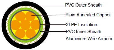
CABLE CONSTRUCTION
Conductor: Plain annealed copper wire, stranded according to IEC 60228 class 2.
Insulation: Extruded cross-linked XLPE compound.
Inner sheath : PVC Compound
Armouring : Aluminium Wire
Outer Sheath : Thermoplastic PVC compound .
COLOUR CODE
Insulation Colour: Natural
Sheath Colour: Black (other colors upon request)
Physical AND THERMAL PROPERTIES
Temperature Range During Operation: -40°C ~ 70°C
Temperature Range during Installation : -5°C ~ 50°C
Minimum Bending Radius: 8 x OD
Electrical PROPERTIES
Dielectric Test:3500 Vr.m.s.x 5’(core/core)
Insulation Resistance:500 MΩ x km ( at 20°C )
Short circuit Temperature:250°C ( up to5secs)
CONSTRUCTION PARAMETERS
| Cable Code |
Conductor | Diameter Under Armour |
Armour Wire Diameter | Nominal Overall Diameter |
Approx. Weight | |
| No. of CoreX CrossSection | No./Nominal Diameter of Strands |
|||||
| mm2 | No./mm | mm | mm | mm | kg/km | |
| FFGD3001RVMV-R 1G70 | 1x70 | 19/2.14 | 15.4 | 1.25 | 21.5 | 960 |
| FFGD3001RVMV-R 1G95 | 1x95 | 19/2.52 | 17.3 | 1.25 | 23.4 | 1240 |
| FFGD3001RVMV-R 1G120 | 1x120 | 37/2.03 | 19.1 | 1.6 | 25.9 | 1650 |
| FFGD3001RVMV-R 1G150 | 1x150 | 37/2.25 | 21.1 | 1.6 | 27.9 | 1970 |
| FFGD3001RVMV-R 1G185 | 1x185 | 37/2.52 | 23.2 | 1.6 | 30.1 | 2390 |
| FFGD3001RVMV-R 1G240 | 1x240 | 61/2.25 | 26.2 | 1.6 | 33.2 | 3040 |
| FFGD3001RVMV-R 1G300 | 1x300 | 61/2.52 | 28.8 | 1.6 | 35.8 | 3790 |
| FFGD3001RVMV-R 1G400 | 1x400 | 61/2.85 | 32.7 | 2.0 | 40.9 | 4790 |
| FFGD3001RVMV-R 1G500 | 1x500 | 61/3.20 | 36.2 | 2.0 | 44.6 | 5880 |
| FFGD3001RVMV-R 1G630 | 1x630 | 127/2.52 | 40.6 | 2.0 | 49.2 | 7400 |
| FFGD3001RVMV-R 1G800 | 1x800 | 127/2.85 | 45.7 | 2.5 | 55.7 | 9500 |
| FFGD3001RVMV-R 1G1000 | 1x1000 | 127/3.20 | 50.6 | 2.5 | 61.0 | 11750 |
Electrical PROPERTIES
Conductor Operating Temperature : 90°C
Ambient Temperature : 30°C
Current-Carrying Capacities (Amp)
| Conductor cross- sectional area |
Reference Method1(clipped direct) | Reference Method11(ona perforated horizontalcabletrayor Reference Method 13[freeair]) |
Reference Method 12(free air) |
Insingle- wayducts |
Laiddirectin ground |
||||
| 2 cables, single- phase a.c.ord.c. | 3 or 4cables, 3-phasea.c. | 2 cables, single- phase a.c.ord.c. | 3 or 4cables, 3-phasea.c. | 3cables 3-phase a.c.trefoiltouching | 2 cables, single- phase a.c.ord.c. | 3 or 4cables, 3-phasea.c. | 2 cables, single- phase a.c.ord.c. | 3 or 4cables, 3-phasea.c. | |
| 1 | 2 | 3 | 4 | 5 | 6 | 7 | 8 | 9 | 10 |
| mm2 | A | A | A | A | A | A | A | A | A |
| 70 | 303 | 277 | 322 | 293 | 285 | 310 | 280 | 340 | 290 |
| 95 | 367 | 333 | 389 | 352 | 346 | 365 | 330 | 405 | 345 |
| 120 | 425 | 383 | 449 | 405 | 402 | 410 | 370 | 460 | 389 |
| 150 | 488 | 437 | 516 | 462 | 463 | 445 | 405 | 510 | 435 |
| 185 | 557 | 496 | 587 | 524 | 529 | 485 | 440 | 580 | 490 |
| 240 | 656 | 579 | 689 | 612 | 625 | 550 | 500 | 670 | 560 |
| 300 | 755 | 662 | 792 | 700 | 720 | 610 | 550 | 750 | 630 |
| 400 | 853 | 717 | 899 | 767 | 815 | 640 | 580 | 830 | 700 |
| 500 | 962 | 791 | 1016 | 851 | 918 | 690 | 620 | 910 | 770 |
| 630 | 1082 | 861 | 1146 | 935 | 1027 | 750 | 670 | 1000 | 840 |
| 800 | 1170 | 904 | 1246 | 987 | 1119 | 828 | 735 | 1117 | 931 |
| 1000 | 1261 | 961 | 1345 | 1055 | 1214 | 919 | 811 | 1254 | 1038 |
Voltage Drop (Per Amp Per Meter)
| Conductor cross-sectionalarea | 2 cablesd.c. | 2cables single-phasea.c. | 3 or 4 cables three-phase a.c. | 2 cables single phasea.c. |
3 or 4 cables,3-phase a.c.touching | |||||||||
| Reference Method 1 & 11 (touching) | Reference Method1, 11 & 12 (intrefoiltouching) | Reference Method 1 &11(Flattouching) | In ducts | In ground | In ducts | In ground | ||||||||
| 1 | 2 | 3 | 4 | 5 | 6 | 7 | 8 | 9 | ||||||
| mm2 | mV/A/m | mV/A/m | mV/A/m | mV/A/m | mV/A/m | mV/A/m | mV/A/m | mV/A/m | ||||||
| r | x | z | r | x | z | r | x | z | ||||||
| 70 | 0.67 | 0.68 | 0.20 | 0.71 | 0.59 | 0.17 | 0.62 | 0.6 | 0.25 | 0.65 | 0.80 | 0.70 | 0.70 | 0.61 |
| 95 | 0.49 | 0.51 | 0.195 | 0.55 | 0.44 | 0.17 | 0.47 | 0.46 | 0.24 | 0.52 | 0.65 | 0.53 | 0.56 | 0.46 |
| 120 | 0.39 | 0.41 | 0.190 | 0.45 | 0.35 | 0.165 | 0.39 | 0.38 | 0.24 | 0.44 | 0.55 | 0.43 | 0.48 | 0.37 |
| 150 | 0.31 | 0.33 | 0.185 | 0.38 | 0.29 | 0.160 | 0.33 | 0.31 | 0.23 | 0.39 | 0.50 | 0.37 | 0.43 | 0.32 |
| 185 | 0.25 | 0.27 | 0.185 | 0.33 | 0.23 | 0.160 | 0.28 | 0.26 | 0.23 | 0.34 | 0.45 | 0.31 | 0.39 | 0.27 |
| 240 | 0.195 | 0.21 | 0.180 | 0.28 | 0.18 | 0.155 | 0.24 | 0.21 | 0.22 | 0.30 | 0.40 | 0.26 | 0.35 | 0.23 |
| 300 | 0.155 | 0.17 | 0.175 | 0.25 | 0.145 | 0.150 | 0.21 | 0.17 | 0.22 | 0.28 | 0.37 | 0.24 | 0.32 | 0.21 |
| 400 | 0.115 | 0.145 | 0.170 | 0.22 | 0.125 | 0.150 | 0.195 | 0.160 | 0.21 | 0.27 | 0.35 | 0.21 | 0.30 | 0.19 |
| 500 | 0.093 | 0.125 | 0.170 | 0.21 | 0.105 | 0.145 | 0.180 | 0.145 | 0.20 | 0.25 | 0.33 | 0.20 | 0.28 | 0.18 |
| 630 | 0.073 | 0.105 | 0.165 | 0.195 | 0.092 | 0.145 | 0.170 | 0.135 | 0.195 | 0.24 | 0.30 | 0.19 | 0.26 | 0.17 |
| 800 | 0.056 | 0.090 | 0.160 | 0.190 | 0.086 | 0.140 | 0.165 | 0.130 | 0.180 | 0.23 | 0.28 | 0.18 | 0.24 | 0.16 |
| 1000 | 0.045 | 0.092 | 0.155 | 0.180 | 0.080 | 0.135 | 0.155 | 0.125 | 0.170 | 0.21 | 0.26 | 0.17 | 0.22 | 0.15 |
r = conductor resistance at operating temperature
x = reactance
z = impedance