


| Airport Cable | |||
![]() 2491X to BS 6004 Cables
2491X to BS 6004 Cables
450/750V PVC Insulated, PVC Sheathed, Screened Controlling Cables (2 core)
RE-Y(St)Y (CU/PVC/OS/PVC 450/750V Class 5)
APPLICATION
The Airprot cables unarmoured versions (Part 2 Type 1) are generally use for indoor installation and suitable for
wet and damp areas. Generally used within industrial process manufacturing plants for communication, data and
voice transmission signals and services, Also used for the interconnection of electrical equipment and
instruments, typically in chemical or petrolchemical industry.
STANDARDS
Basic design to BS 5308 Part 2 Type 1
FIRE PERFORMANCE
| FlameRetardance (SingleVerticalWireTest)** | EN60332-1-2; IEC60332-1-2; BSEN 60332-1-2; VDE0482-332-1; NBN C30-004 (cat.F1);NF C32-070-2.1(C2); CEI 20-35/1-2; EN 50265-2-1*; DIN VDE 0482-265-2-1* |
| Reduced FirePropagation(Vertically-mountedbundledwires &cabletest)** | EN60332-3-24 (cat.C); IEC60332-3-24;BSEN60332-3-24;VDE0482-332-3;NBN C30-004 (cat.F2);NF C32-070-2.2(C1);CEI 20-22/3-4; EN 50266-2-4*; DIN VDE 0482-266-2-4 |
Note:
Asterisk * denotes superseded standard
Asterisk ** denotes that the standard compliance is optional, depending on the oxygen index of the PVC
compound and the cable design.
VOLTAGE RATING
450/750V
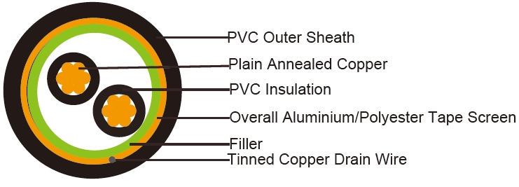
CABLE CONSTRUCTION
Conductor: Plain annealed copper wire, stranded according to BS 6360 Class 5
Insulation: PVC (polyvinyl chloride), type TI1 to BS 6746
Filler, binder: PETP transparent tape
Overall Screen: Aluminium/polyester tape is applied over the laid up pairs metallic side down in contact with
tinned copper drain wire, 0.5mm²
Outer Sheath: PVC Sheath, type TM 1 or type 6 to BS 6746
COLOUR CODE
Insulation Colour as per BS 7671
Black with Arabic numbers printing in white colour
Outer sheath: Black or as order
Physical AND THERMAL PROPERTIES
Operating Temperature: -40˚C up to + 70˚C( fixed installation)
0˚C to +50˚C(during operation )
Minimum Bending Radius: 5 x Overall Diameter
Insulation Resistance Min.: 25 Mohm/km
CONSTRUCTION PARAMETERS
| Conductor | RE-Y(St)Y | ||||||
| No.of CoreXCross Section |
No./ Nominal Diameterof Strands |
Conductor Diameter |
Nominal Insulation Thickness |
Nominal Aluminium TapeScreen Thickness |
Nominal Sheath Thickness |
Nominal Overall Diameter |
Approx. Weight |
| Noxmm2 | No./mm | mm | mm | mm | mm | mm | kg/km |
| 2x1.5 | 30/0.25 | 1.6 | 0.7 | 0.05 | 0.9 | 8.4 | 117 |
Electrical PROPERTIES
Operating Temperature: -40˚C up to + 70˚C( fixed installation)
0˚C to +50˚C(during operation )
Minimum Bending Radius: 5 x Overall Diameter
Insulation Resistance Min.: 25 Mohm/km
Current-Carrying Capacities (Amp)
Conductor |
Reference insulatingwalletc) |
Reference trunkingetc) |
Reference |
Reference |
Reference |
||
Horizontalflat spaced |
Verticalflat spaced |
Trefoil |
|||||
2cables, single- phase |
3 or 4cables, 3-phasea.c. |
2 |
3 or 4cables, 3-phasea.c. |
2cables, single- phase |
3 or 4cables, 3-phase |
2cables,single- phase |
3 or 4cables, |
2cables, single- phase a.c.ord.c.or 3cables |
2 |
3cables, trefoil |
|
1 |
2 |
3 |
4 |
5 |
6 |
7 |
8 |
9 |
10 |
11 |
12 |
mm2 |
A |
A |
A |
A |
A |
A |
A |
A |
A |
A |
A |
1.5 |
18 |
17 |
22 |
19 |
25 |
23 |
- |
- |
- |
- |
- |
Voltage Drop (Per Amp Per Meter)
| Nominal Cross Section Area |
2cables d.c. | 2cables, single-phasea.c. |
3or 4cables,3-phase a.c. | |||
| Ref.Methods 3and 4 (enclosed in conduitetc, inoron a wall) |
Ref. Methods1 and11 (clipped director ontray stouching) |
Ref.Methods3 and 4 (enclosed inconduitetc, inoron a wall) |
Ref.Methods1, | Ref.Methods1and11 | ||
| 11 and12 (intrefoil) | (Flat and touching) | |||||
| 1 | 2 | 3 | 4 | 5 | 6 | 7 |
| mm2 | mV/A/m | mV/A/m | mV/A/m | mV/A/m | mV/A/m | mV/A/m |
| 1.5 | 31 | 31 | 27 | 27 | 27 | 27 |