


| Airport Cable | |||
![]() 2491X to BS 6004 Cables
2491X to BS 6004 Cables
450/750V PVC Insulated, PVC Sheathed Power Cables (2 core & 3 core)
FGD200 07VV-F (CU/PVC/PVC 450/750V Class 5)
APPLICATION
Airprot cables are mainly used in power stations, mass transit underground passenger systems, airports,
petrochemical plants, hotels, hospitals, and high-rise buildings. The cables can be offered with the ability to
restrict the propagation of the flame in the event of a fire.
STANDARDS
Basic design to BS 6004, BS6500
FIRE PERFORMANCE
| FlameRetardance (SingleVerticalWireTest)** | EN60332-1-2; IEC60332-1-2; BSEN 60332-1-2; VDE0482-332-1; NBN C30-004 (cat.F1);NF C32-070-2.1(C2); CEI 20-35/1-2; EN 50265-2-1*; DIN VDE 0482-265-2-1* |
| Reduced FirePropagation(Vertically-mountedbundledwires &cabletest)** | EN60332-3-24 (cat.C); IEC60332-3-24;BSEN60332-3-24;VDE0482-332-3;NBN C30-004 (cat.F2);NF C32-070-2.2(C1);CEI 20-22/3-4; EN 50266-2-4*; DIN VDE 0482-266-2-4 |
Note:
Asterisk * denotes superseded standard
Asterisk ** denotes that the standard compliance is optional, depending on the oxygen index of the PVC
compound and the cable design.
VOLTAGE RATING
450/750V
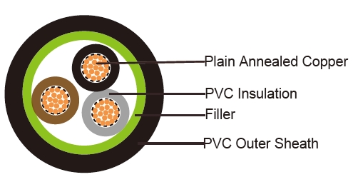
CABLE CONSTRUCTION
Conductor: Plain annealed copper wire, stranded according to BS 6360 Class 5
Insulation: PVC insulation type TI1 to BS 7655
Filler, binder (if any): PP, PET
Outer Sheath: PVC sheath type T6 to BS 7655
COLOUR CODE
Insulation Colour as per BS7671
| withearth conductor | withoutearth conductor | |
| 2Cores | - | Brown,Blue |
| 3Cores | Yellow/Green,Brown,Blue | Brown,Gray,Black |
| 4Cores | Yellow/Green,Brown,Gray,Black | Brown,Gray,Black,Blue |
| 5Cores | Yellow/Green,Brown,Gray,Black,Blue | Brown,Gray,Black,Blue,Black |
| above 5 Cores | Yellow/Green,BlackNumbers | Black Numbers |
Outer sheath: Black or as order
Physical AND THERMAL PROPERTIES
Operating temperature: -15º C to +70º C
Short circuit temperature: +160º C
Minimum bending radius: 4x Overall Diameter
Insulation resistance: 20 MΩxkm
CONSTRUCTION PARAMETERS
| Conductor | fGD20007VV-f | ||||||
No.of |
No./ |
Conductor |
Nominal |
Nominal |
Nominal |
Max.DC resistance ofconductor @20°C |
Approx. Weight |
Noxmm2 |
No./mm |
mm | mm | mm | mm | Ω/km |
kg/km |
2x1.5 |
30/0.25 |
1.6 | 0.7 | 0.9 | 9.3 | 12.1 |
108 |
3x2.5 |
50/0.25 |
2.0 | 0.8 | 1.2 | 10.8 |
7.41 |
179 |
Electrical PROPERTIES
Conductor Operating Temperature : 90°C
Ambient Temperature : 30°C
Current-Carrying Capacities (Amp)
Conductor |
Reference Method4 |
Reference Method3 (enclosed inconduit ona wallorin trunkingetc) |
Reference |
Reference |
Reference |
||
Horizontal |
Vertical |
Trefoil |
|||||
| 2cables, single- phase a.c.ord.c. | 3 or 4cables, 3-phasea.c. | 2cables, single- phase a.c.ord.c | 3 or 4cables, 3-phasea.c. | 2cables, single- phase a.c.or d.c. flat andtouching |
3 or 4cables, 3-phase a.c. flat andtouching or trefoil |
2 cables, single- phase a.c.or d.c.orflat and touching |
3 or 4cables, 3-phase a.c. flat andtouching or trefoil |
2cables, single- phase a.c.ord.c.or 3cablesthree phase |
2cables, single- phase a.c.ord.c.or 3 cables three phase |
3 cables, trefoil 3- phasea.c. | |
| 1 | 2 | 3 | 4 | 5 | 6 | 7 | 8 | 9 | 10 | 11 | 12 |
mm2 |
A | A | A | A | A | A | A | A | A | A | A |
| 1.5 | 18 | 17 | 22 |
19 | 25 | 23 | - | - | - | - | - |
| 2.5 | 24 | 23 | 30 |
26 | 34 | 31 | - | - | - | - | - |
Voltage Drop(PerAmp PerMeter)
| Nominal CrossSection Area |
2cables d.c. | 2cables,single-phasea.c. | 3or 4cables,3-phase a.c. | |||
| Ref.Methods3 and 4 (enclosed inconduitetc, inoron a wall) |
Ref.Methods1 and11(clipped director ontray stouching) |
Ref.Methods3 and 4 (enclosed inconduitetc ,inoron a wall) |
Ref.Methods1, | Ref.Methods1and11 | ||
| 11 and12 (intrefoil) | (Flat and touching) | |||||
| 1 | 2 | 3 | 4 | 5 | 6 | 7 |
| mm2 | mV/A/m | mV/A/m | mV/A/m | mV/A/m | mV/A/m | mV/A/m |
| 1.5 | 31 | 31 | 27 | 27 | 27 | 27 |
| 2.5 | 19 | 19 | 16 | 16 | 16 | 16 |