


| Airport Cable | |||
![]() FFX300 1mRZ1MZ1-R (CU/MGT+XLPE/LSZH/AWA/LSZH 600/1000V Single Core)
FFX300 1mRZ1MZ1-R (CU/MGT+XLPE/LSZH/AWA/LSZH 600/1000V Single Core)
600/1000V Mica/XLPE Insulated, LSZH Sheathed, Armoured Power Cables (Single Core)
APPLICATION
Airprot cables is designed for areas where the integrity of the electrical properties circuit is critical in maintaining
power supply. Applications can be found in emergency lightings, control and power circuits, power stations, fire
alarm systems, underground tunnels, communications systems, sewage treatment plants, lifts, escalators, and
high-rise buildings.
STANDARDS
Basic design to BS 7846
FIRE PERFORMANCE
| Circuit Integrity | IEC60331-21;BS6387 CWZ;DINVDE0472-814(FE180); CEI20-36/2-1; SS229-1;NBNC30-004 (cat.F3);NF C32-070-2.3(CR1) |
| SystemCircuitIntegrity | DIN4102-12, E30depending on lay system |
| Flame Retardance (SingleVerticalWireTest) | EN60332-1-2; IEC60332-1-2; BSEN60332-1-2;VDE0482-332-1 ; NBNC30-004 (cat.F1); NF C32-070-2.1(C2); CEI 20-35/1-2; EN50265-2-1*;DIN VDE 0482-265-2-1* |
| Reduced FirePropagation(Vertically-mountedbundledwires &cabletest) | EN60332-3-24 (cat.C); IEC60332-3-24;BSEN60332-3-24;VDE0482-332-3;NBNC30-004(cat.F2);NFC32-070-2.2(C1);CEI 20-22/3-4; EN 50266-2-4*; DIN VDE 0482-266-2-4 |
| Halogen Free | IEC60754-1; EN 50267-2-1; DIN VDE 0482-267-2-1;CEI20-37/2-1;BS6425-1* |
| NoCorrosive GasEmission | IEC60754-2; EN 50267-2-2; DIN VDE 0482-267-2-2;CEI20-37/2-2;BS6425-2* |
| MinimumSmokeEmission | IEC61034-1&2; EN 61034 -1&2; DIN VDE 0482-1034-1&2;CEI20-37/3-1&2; EN50268-1&2*;BS 7622-1&2* |
| NoToxic Gases | NES02-713;NF C 20-454 |
Note: Asterisk * denotes superseded standard.
VOLTAGE RATING
600/1000 V
CABLE CONSTRUCTION
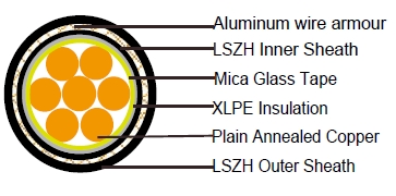
Conductor: Plain annealed copper wire, stranded according to IEC 60228 class 2.
Insulation: Mica glass tape covered by extruded cross-linked XLPE compound
Inner Sheath :Thermoplastic LSZH compound type LTS3 as per BS 7655-6.1
Armouring : Aluminum wire armour
Outer Sheath:Thermoplastic LSZH compound type LTS3 as per BS 7655-6.1
COLOUR CODE
Insulation Colour : Natural
Sheath Colour: Black (other colors upon request)
Physical AND THERMAL PROPERTIES
Temperature Range During Operation: -30°C ~ 90°C
Temperature Range during Installation : -5°C ~ 50°C
Minimum Bending Radius: 8 x OD
Electrical PROPERTIES
Dielectric Test: 3500 Vr.m.s.x 5’(core/core)
Insulation Resistance:1000 MΩ x km ( at20°C )
Short Circuit Temperature:250°C ( up to5secs)
CONSTRUCTION PARAMETERS
| Cable Code |
Conductor | Approx. Overall Diameter | Approx. Weight | |||
| No.of Core ×Cross Section |
No./ Nominal Diameter of Strands |
Dia.of Conductor |
Nominal Insulation Thickness |
|||
| mm2 | No./mm | mm | mm | mm | kg/km | |
| FFX300 1mRZ1MZ1-R1G1.5 | 1×1.5 | 7/0.53 | 1.59 | 0.7 | - | - |
| FFX300 1mRZ1MZ1-R1G2.5 | 1×2.5 | 7/0.67 | 2.01 | 0.7 | - | - |
| FFX300 1mRZ1MZ1-R1G4 | 1×4 | 7/0.85 | 2.55 | 0.7 | - | - |
| FFX300 1mRZ1MZ1-R1G6 | 1×6 | 7/1.04 | 3.12 | 0.7 | - | - |
| FFX300 1mRZ1MZ1-R1G10 | 1×10 | 7/1.35 | 4.05 | 0.7 | - | - |
| FFX300 1mRZ1MZ1-R1G16 | 1×16 | 7/1.70 | 5.1 | 0.7 | - | - |
| FFX300 1mRZ1MZ1-R1G25 | 1×25 | 7/2.14 | 6.42 | 0.9 | - | - |
| FFX300 1mRZ1MZ1-R1G35 | 1×35 | 19/1.53 | 7.65 | 0.9 | - | - |
| FFX300 1mRZ1MZ1-R1G50 | 1×50 | 19/1.78 | 8.9 | 1 | 18.5 | 780 |
| FFX300 1mRZ1MZ1-R1G70 | 1×70 | 19/2.14 | 10.7 | 1.1 | 20.5 | 1010 |
| FFX300 1mRZ1MZ1-R1G95 | 1×95 | 19/2.52 | 12.6 | 1.1 | 23 | 1320 |
| FFX300 1mRZ1MZ1-R1G120 | 1×120 | 37/2.03 | 14.21 | 1.2 | 24.5 | 1610 |
| FFX300 1mRZ1MZ1-R1G150 | 1×150 | 37/2.25 | 15.75 | 1.4 | 27 | 2010 |
| FFX300 1mRZ1MZ1-R1G185 | 1×185 | 37.2.52 | 17.64 | 1.6 | 29.5 | 2440 |
| FFX300 1mRZ1MZ1-R1G240 | 1×240 | 61/2.25 | 20.25 | 1.7 | 34.5 | 3060 |
| FFX300 1mRZ1MZ1-R1G300 | 1×300 | 61/2.52 | 22.68 | 1.8 | 36.9 | 3690 |
| FFX300 1mRZ1MZ1-R1G400 | 1×400 | 65/2.85 | 25.65 | 2 | 41.5 | 4780 |
| FFX300 1mRZ1MZ1-R1G500 | 1×500 | 61/3.20 | 28.8 | 2.2 | 45.5 | 5970 |
| FFX300 1mRZ1MZ1-R1G630 | 1×630 | 127/2.52 | 32.76 | 2.4 | 50.5 | 7530 |
| FFX300 1mRZ1MZ1-R1G800 | 1×800 | 127/2.85 | 37.05 | 2.6 | 56.8 | 9680 |
| FFX300 1mRZ1MZ1-R1G1000 | 1×1000 | 127/3.20 | 41.6 | 2.8 | 61.5 | 11980 |
ElectricAl PROPERTIES
Conductor Operating Temperature : 90°C
Ambient Temperature : 30°C
Current-Carrying Capacities (Amp)
| Nominal Cross Section Area |
Reference Method1 (clipped direct) |
Reference Method11(on perforated cabletray) |
Reference Method 12(free air) |
Insingle- wayducts |
Laiddirectin ground |
||||
| 2cables singlephase a.c. or d.c.flat and touching | 3 or 4cables 3-phase a.c. flat andtouching | 2cables singlephase a.c. or d.c.flat and touching |
3 or 4cables 3-phase a.c. flat and touching |
3cables 3-phase a.c.trefoil touching |
2cables singlephase a.c. ord.c. ducts touching |
3cables 3-phase a.c.trefoil touching |
2cables singlephase a.c. ord.c. touching |
3cables 3-phase a.c.trefoil touching |
|
| 1 | 2 | 3 | 4 | 5 | 6 | 7 | 8 | 9 | 10 |
| mm2 | A | A | A | A | A | A | A | A | A |
| 50 | 237 | 220 | 253 | 232 | 222 | 255 | 235 | 275 | 235 |
| 70 | 303 | 277 | 322 | 293 | 285 | 310 | 280 | 340 | 290 |
| 95 | 367 | 333 | 389 | 352 | 346 | 365 | 330 | 405 | 345 |
| 120 | 425 | 383 | 449 | 405 | 402 | 410 | 370 | 460 | 389 |
| 150 | 488 | 437 | 516 | 462 | 463 | 445 | 405 | 510 | 435 |
| 185 | 557 | 496 | 587 | 524 | 529 | 485 | 440 | 580 | 490 |
| 240 | 656 | 579 | 689 | 612 | 625 | 550 | 500 | 670 | 560 |
| 300 | 755 | 662 | 792 | 700 | 720 | 610 | 550 | 750 | 630 |
| 400 | 853 | 717 | 899 | 767 | 815 | 640 | 580 | 830 | 700 |
| 500 | 962 | 791 | 1016 | 851 | 918 | 690 | 620 | 910 | 770 |
| 630 | 1082 | 861 | 1146 | 935 | 1027 | 750 | 670 | 1000 | 840 |
| 800 | 1170 | 904 | 1246 | 987 | 1119 | 828 | 735 | 1117 | 931 |
| 1000 | 1261 | 961 | 1345 | 1055 | 1214 | 919 | 811 | 1254 | 1038 |
Voltage Drop (Per Amp Per Meter)
| Nominal Cross Section Area 1 |
2 cables d.c. 2 | 2cables single- phase a.c. |
3or 4cables three- phasea.c. |
2cables single phase a.c. |
3 or 4cables,3-phasea.c. touching |
|||||||||
| Reference Method1& 11(touching) | Reference Method 1,11 & 12 (intrefoiltouching) |
Reference Method1&11 (Flat touching) |
Inducts 6 | Inground 7 | Inducts 8 | Inground 9 | ||||||||
| 3 | 4 | 5 | ||||||||||||
| mm2 | mV/A/m | mV/A/m | mV/A/m | mV/A/m | mV/A/m | mV/A/m | mV/A/m | mV/A/m | ||||||
| r | x | z | r | x | z | r | x | z | ||||||
| 50 | 0.98 | 0.99 | 0.21 | 1 | 0.86 | 0.18 | 0.87 | 0.84 | 0.25 | 0.88 | 1.1 | 0.99 | 0.93 | 0.86 |
| 70 | 0.67 | 0.68 | 0.2 | 0.71 | 0.59 | 0.17 | 0.62 | 0.6 | 0.25 | 0.65 | 0.8 | 0.7 | 0.7 | 0.61 |
| 95 | 0.49 | 0.51 | 0.195 | 0.55 | 0.44 | 0.17 | 0.47 | 0.46 | 0.24 | 0.52 | 0.65 | 0.53 | 0.56 | 0.46 |
| 120 | 0.39 | 0.41 | 0.19 | 0.45 | 0.35 | 0.165 | 0.39 | 0.38 | 0.24 | 0.44 | 0.55 | 0.43 | 0.48 | 0.37 |
| 150 | 0.31 | 0.33 | 0.185 | 0.38 | 0.29 | 0.16 | 0.33 | 0.31 | 0.23 | 0.39 | 0.5 | 0.37 | 0.43 | 0.32 |
| 185 | 0.25 | 0.27 | 0.185 | 0.33 | 0.23 | 0.16 | 0.28 | 0.26 | 0.23 | 0.34 | 0.45 | 0.31 | 0.39 | 0.27 |
| 240 | 0.195 | 0.21 | 0.18 | 0.28 | 0.18 | 0.155 | 0.24 | 0.21 | 0.22 | 0.3 | 0.4 | 0.26 | 0.35 | 0.23 |
| 300 | 0.155 | 0.17 | 0.175 | 0.25 | 0.145 | 0.15 | 0.21 | 0.17 | 0.22 | 0.28 | 0.37 | 0.24 | 0.32 | 0.21 |
| 400 | 0.115 | 0.145 | 0.17 | 0.22 | 0.125 | 0.15 | 0.195 | 0.16 | 0.21 | 0.27 | 0.35 | 0.21 | 0.3 | 0.19 |
| 500 | 0.093 | 0.125 | 0.17 | 0.21 | 0.105 | 0.145 | 0.18 | 0.145 | 0.2 | 0.25 | 0.33 | 0.2 | 0.28 | 0.18 |
| 630 | 0.073 | 0.105 | 0.165 | 0.195 | 0.092 | 0.145 | 0.17 | 0.135 | 0.195 | 0.24 | 0.3 | 0.19 | 0.26 | 0.17 |
| 800 | 0.056 | 0.09 | 0.16 | 0.19 | 0.086 | 0.14 | 0.165 | 0.13 | 0.18 | 0.23 | 0.28 | 0.18 | 0.24 | 0.16 |
| 1000 | 0.045 | 0.092 | 0.155 | 0.18 | 0.08 | 0.135 | 0.155 | 0.125 | 0.17 | 0.21 | 0.26 | 0.17 | 0.22 | 0.15 |
Note: r = conductor resistance at operating temperature
x = reactance
z = impedance