


| Telephone Cables | ||||||||||||
|
||||||||||||
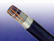
![]() Solid PE Insulated & AP Sheathed (ALPETH) Air Core Cables to GR-421
Solid PE Insulated & AP Sheathed (ALPETH) Air Core Cables to GR-421
Application
The cables are designed for use as subscriber distribution cables and as connection between central offices. The
cables are suitable for installation in ducts, direct burial in the ground and also for aerial installation with integral
suspension strand. An armoured option is offered for direct burial installations. A figure-8 self support option is
offered for aerial installation.
Standards
Telcordia (Bellcore) GR-421
Construction
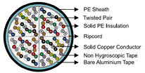
Conductors: Solid annealed bare copper, 0.4/0.5/0.63/0.9mm, as per ASTM B-3/class 1 of IEC 60228
Insulation: Solid medium or high density polyethylene as per ASTM D 1248/IEC 60708
Twisted Pairs: Insulated conductors are twisted into pairs with varying lay length to minimize crosstalk
Cabling Element: Twisted Pairs
Cable Core Assembly:Cables with up to 400 pairs are composed of 25-pair units or 12/13-pair units; cables
with over 400 pairs are composed of 50 or 100-pair units. Any extra pairs form a separate unit. Units are
identified by colour coded binders. Construction is per GR-421 given in Cable Make Up Diagram.
Core Wrapping: One or more non-hygroscopic polyester tapes are helically or longitudinally laid with an overlap.
These tapes furnish thermal, mechanical as well as high dielectric protection between shielding and individual
conductors
Moisture Barrier: A layer of bare aluminium tape (0.2mm/8mil) is applied longitudinally with overlap over the
cable core to provide 100% electrical shielding coverage and ensures a barrier against water vapor. In cables
with more than 200 pairs, the aluminum tape may be corrugated for improved cable flexibility
Sheath: Black low density polyethylene as per ASTM D 1248/IEC 60708, being able to withstand exposure to
sunlight, temperature variations, ground chemicals and other environmental contaminants
Ripcord: Ripcord may be provided for slitting the sheath longitudinally to facilitate its removal
Spare Pairs (optional): Spare pairs may be incorporated for large pair cables
Continuity Wire (optional): One tinned copper drain wire may be longitudinally laid to ensure electrical
continuity of the screen
Optional Construction
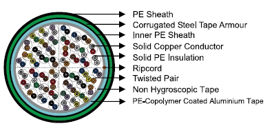
Armoured Cable
0.15mm thick corrugated steel tape armour is applied with an overlap over an optional inner polye-thylene
sheath. An outer polyethylene sheath is applied over the armour
Self-Support Cables
A 7-strand galvanized steel strand is used as support wire. Black polyethylene sheath covers both
core and support wire in a figure-8 construction
Aabbreviations
LAP (CAP):Copolymer coated aluminium tape + PE sheath
LAPSP (CAPSP):LAP sheath + steel tape armour + PE sheath
AP (ALPETH): Bare aluminium tape + PE sheath
PAP: PE inner sheath + bare aluminium tape + PE sheath
PASP: PE inner sheath + bare aluminium tape + steel tape armour + PE outer sheath
ASP (STAPETH): Bare aluminium tape + steel tape armour + PE outer sheath
CACSP: Copolymer coated aluminum tape + copolymer coated steel tape armour + PE outer sheath
LAPSP: Copolymer coated aluminum tape +PE inner sheath + steel tape armour + PE outer sheath
FIGURE 8 LAP: Copolymer coated aluminum tape + PE outer sheath + self supporting
Electrical Properties
| Nominal Conductor Diameter | mm | 0.4 | 0.5 | 0.63 | 0.9 |
| Conductor Gauge Size | AWG | 26 | 24 | 22 | 19 |
| Maximum Average DC Resistance | Ω/km / Ω/mile | 140/225 | 87/140 | 55/88.6 | 27.0/43.4 |
| Maximum Individual DC Resistance | Ω/km / Ω/mile | 144.2/232 | 89.5/144 | 56.5/91.0 | 28.0/45.0 |
| Minimum Insulation Resistance @500V DC | MΩ.km / MΩ.mile | 1600/1000 | 1600/1000 | 1600/1000 | 1600/1000 |
| Maximum Average Resistance Unbalance | % | 1.5 | 1.5 | 1.5 | 1.5 |
| Maximum Individual Resistance Unbalance | % | 5 | 5 | 5 | 5 |
| Average Mutual Capacitance | nF/km / nF/kft | 48.5-54.0 /14.8-16.5 | 48.5-54.0 /14.8-16.5 | 48.5-54.0 /14.8-16.5 | 48.5-54.0 /14.8-16.5 |
| Maximum Individual Mutual Capacitance | nF/km / nF/kft | 57/17.4 | 57/17.4 | 57/17.4 | 57/17.4 |
| Maximum Individual Capacitance Unbalance pair-to-pair | pF/km / pF/kft | 145/44 | 145/44 | 145/44 | 145/44 |
| Capacitance Unbalance RMS pair-to-pair | pF/km / pF/kft | 45/13.7 | 45/13.7 | 45/13.7 | 45/13.7 |
| Maximum Individual Capacitance Unbalance pair-to-ground |
pF/km / pF/kft | 2625/800 | 2625/800 | 2625/800 | 2625/800 |
| Maximum Average Capacitance Unbalance pair-to-ground |
pF/km / pF/kft | 574/175 | 574/175 | 574/175 | 574/175 |
| Maximum Conductor Loop Resistance @20°C | Ω/km / Ω/mile | 300/482 | 192/309 | 114/183.6 | 60/96.4 |
| Impedance @1KHz | Ω | 994 | 796 | 660 | 445 |
| Impedance @100KHz | Ω | 147 | 134 | 125 | 122 |
| Impedance @512KHz | Ω | 120 | 118 | 117 | 116 |
| Impedance @1MHz | Ω | 117 | 115 | 114 | 113 |
| Maximum Average Attenuation @0.8KHz | dB/km / dB/kft | 1.64/0.5 | 1.30/0.39 | 1.04/0.32 | 0.74/0.22 |
| Maximum Average Attenuation @1KHz | dB/km / dB/kft | 1.68/0.51 | 1.35/0.41 | 1.08/0.33 | 0.76/0.23 |
| Maximum Average Attenuation @3KHz | dB/km / dB/kft | 3.18/0.97 | 2.52/0.77 | 2.01/0.61 | 1.42/0.43 |
| Maximum Average Attenuation @150KHz | dB/km / dB/kft | 11.4/3.47 | 8.3/2.53 | 6.2/1.89 | 4.4/1.34 |
| Maximum Average Attenuation @772KHz | dB/km / dB/kft | 24.3/7.4 | 19.4/5.9 | 15.4/4.7 | 10.8/3.3 |
| Maximum Average Attenuation @1000KHz | dB/km / dB/kft | 27.1/8.25 | 21.4/6.52 | 17.5/5.33 | 12.8/3.89 |
| Dielectric Strength | |||||
| Conductor to Conductor (3secs) | V DC | 2400 | 3000 | 4000 | 5000 |
| Conductor to Conductor (3secs) | V DC | 10000 | 10000 | 10000 | 10000 |
| Minimum EL Far-end Cross-talk-Mean Power Sum | |||||
| @150KHz | dB/305m / dB/kft | 61 | 63 | 63 | 65 |
| @772KHz | dB/305m / dB/kft | 47 | 49 | 49 | 57 |
| @1.6MHz | dB/305m / dB/kft | 41 | 42 | 43 | 44 |
| @3.15MHz | dB/305m / dB/kft | 35 | 37 | 37 | 39 |
| @6.3MHz | dB/305m / dB/kft | 29 | 31 | 31 | 33 |
| Minimum Far-end Cross-talk-Worst Pair Power Sum | |||||
| @150KHz | dB/305m / dB/kft | 57 | 57 | 57 | 59 |
| @772KHz | dB/305m / dB/kft | 43 | 43 | 43 | 45 |
| @1.6MHz | dB/305m / dB/kft | 37 | 37 | 37 | 39 |
| @3.15MHz | dB/305m / dB/kft | 31 | 31 | 31 | 33 |
| @6.3MHz | dB/305m / dB/kft | 25 | 25 | 25 | 27 |
| Minimum Near-end Cross-talk-Mean Power Sum | |||||
| @150KHz | dB/305m / dB/kft | 58 | 58 | 58 | 58 |
| @772KHz | dB/305m / dB/kft | 47 | 47 | 47 | 47 |
| @1.6MHz | dB/305m / dB/kft | 43 | 43 | 43 | 43 |
| @3.15MHz | dB/305m / dB/kft | 38 | 38 | 38 | 38 |
| @6.3MHz | dB/305m / dB/kft | 34 | 34 | 34 | 34 |
| Minimum Near-end Cross-talk-Worst Pair Power Sum | |||||
| @150KHz | dB/305m / dB/kft | 53 | 53 | 53 | 53 |
| @772KHz | dB/305m / dB/kft | 42 | 42 | 42 | 42 |
| @1.6MHz | dB/305m / dB/kft | 38 | 38 | 38 | 38 |
| @3.15MHz | dB/305m / dB/kft | 33 | 33 | 33 | 33 |
| @6.3MHz | dB/305m / dB/kft | 29 | 29 | 29 | 29 |
| Nominal Insulation Thickness | mm | 0.175 | 0.2 | 0.26 | 0.3 |
| Nominal Insulated Conductor Diameter | mm | 0.75 | 0.9 | 1.15 | 1.5 |
1 2