| Railway Cables | ||||||||||
|
||||||||||
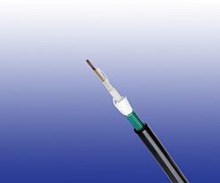
 K209B LSZH Armoured Optical Fiber Cables
Application
K209B LSZH Armoured Optical Fiber Cables are designed for long distance telecommunication and using
optical fibres in urban railways infrastructure. These low smoke halogen-free cables are laid on hooks, pulled
through ducts or cable trays.
Reference Standards
RATP K209B or RATP K209A
Construction

Compact Tube
6 or 12 singlemode optical fibres G652 or multimode fi bers assembled under thermoplastic “peelable” skin. Tube
diameter: 1mm.
Filling
Water-swelling yarns.
Tube
Thermoplastic.
Peripheral Strength Member
Water-swelling glass yarns.
Armour
Corrugated steel tape armour 25/100.
Sheath
LSZH.
Optional
K209A Type: For K209A type, the cables have loose tubes with 6-12 fi bers, steel wire strand as central strength
member, glass yarn reinforced, incorporating a corrugated steel tape armour and an outer UV stabilized LSZH
jacket.
Electrical Characteristics at 20℃
Optical & Geometrical Properties for Single Mode Fibers
| Maximum Attenuation | G652 | |
|---|---|---|
| @1310nm | dB/km | 0.35 |
| @1550nm | dB/km | 0.22 |
| Maximum Chromatic Dispersion | ||
| Between 1260 and 1360nm | ps/(nm/km) | 3.5 |
| Between 1530 and 1565nm | ps/(nm/km) | 19 |
| Zero Dispersion Wavelength | nm | 1310±11 |
| Zero Dispersion Slope | ps/(nm2.km) | 0.09 |
| Numerical Aperture | 0.14 | |
| Point discontinuity | dB | 0.1 |
| PMD (individual fi ber) | ps/km | 0.2 |
| Maximum Cutoff Wavelength | nm | 1260 |
| Cladding Diameter | um | 125±1 |
| Core/Cladding Concentricity Error | um | ≤0.5 |
| Cladding Non Circularity | % | ≤1 |
| Coating Non Circularity | % | ≤6 |
| Proof Test Level | Kpsi (GN/m2) | 100 (0.7) |
| Crush Resistance | N/cm | 300 |
| Maximum Laying Tension | N | 3000 |
Optical & Geometrical Properties for Multimode Fibers
| 50/125 | 62.5/125 | ||
| Maximum Attenuation | |||
| @850nm | dB/km | ≤2.5 | ≤3.0 |
| @1300nm | dB/km | ≤0.7 | ≤0.8 |
| Maximum Chromatic Dispersion | |||
| @850nm | MHz*km | ≥500 | ≥200 |
| @1300nm | MHz*km | ≥800 | ≥500 |
| Zero Dispersion Wavelength | nm | 1310 | 1310 |
| Numerical Aperture | - | 0.20±0.015 | 0.275±0.015 |
| Core Diameter | um | 50±3 | 62.5±3 |
| Cladding Diameter | um | 125±2 | 125±2 |
| Core/Cladding Concentricity Error(Offset) | um | ≤1.5 | ≤1.5 |
| Coating-Clad Concentricity Error(Offset) | um | ≤8 | ≤8 |
| Core Non-Circularity | % | ≤6 | ≤6 |
| Cladding Non-Circularity | % | ≤2 1 | ≤2 1 |
| Coating Diameter | um | 245±10 | 245±10 |
| Proof-Test Level | Kpsi (GN/m2) | 100 (0.7) | 100 (0.7) |
Mechanical and Thermal Properties
Minimum Bending Radius:20×OD
Temperature Range: -40℃ to +60℃ (during operation);
-10℃ +60℃ (during installation)
Dimensions And Weight
K209A
| Cable Code | No. of fibres |
Distribution | Nominal Sheath Thickness mm |
Nominal Overall Diameter mm |
Nominal Weight kg/km |
|---|---|---|---|---|---|
| RO/K209A-ML-C-9-TnxFn-SR-(STA)H | 1-36 | 6 fi bre per tubes | 1.8 | 12 | 190 |
| RO/K209A-ML-C-9-TnxFn-SR-(STA)H | 42-72 | 6/12 fi bre per tubes | 1.8 | 13.5 | 230 |
Tn: Number of tubes; Fn: Number of fi bers in a tube
K209B
| Cable Code | No. of fibres |
No of Tubes x No of Fibers/Tube |
Nominal Sheath Thickness mm |
Nominal Overall Diameter mm |
Nominal Weight kg/km |
|---|---|---|---|---|---|
| Singlemode Fibres From 6 to 36 OF – G652 | |||||
| RO/K209B-ML-C-9-2x6-F-(STA)H | 12 | 2 tubes of 6 OF | 1.8 | 13 | 112 |
| RO/K209B-ML-C-9-4x6-F-(STA)H | 24 | 4 tubes of 6 OF | 1.8 | 13 | 112 |
| RO/K209B-ML-C-9-6x6-F-(STA)H | 36 | 6 tubes of 6 OF | 1.8 | 13 | 112 |
| Singlemode Fibres From 48 to 72 OF – G652 | |||||
| RO/K209B-ML-C-9-8x6-F-(STA)H | 48 | 8 tubes of 6 OF | 2.5 | 15.5 | 230 |
| RO/K209B-ML-C-9-6x12-F-(STA)H | 72 | 6 tubes of 12 OF | 2.8 | 15.5 | 230 |
| Multimode Fibres From 6 to 36 OF – 50/125 | |||||
| RO/K209B-ML-C-9-1x6-F-(STA)H | 6 | 1 tubes of 6 OF | 1.8 | 13 | 112 |
| RO/K209B-ML-C-9-2x6-F-(STA)H | 12 | 2 tubes of 6 OF | 1.8 | 13 | 112 |
Note: The parameters listed above are nominal values as per cable standards. Actual values may vary due to material and manufacturing process variations. For precise specifications or customized requirements, please contact us for further information


