


| Firetox Flame Retardant Cables | |||
![]() Firetox Flame Retardant Cables
Firetox Flame Retardant Cables
600/1000V XLPE Insulated, LSZH Sheathed, Armoured Power Cables to IEC 60502-1 (2-5 Cores)
FTX400 1RZ1MZ1-R (CU/XLPE/LSZH/SWA/LSZH 600/1000V Class 2)
APPLICATION
The cables are mainly used in power stations, mass transit underground passenger systems, airports,
petrochemical plants, hotels, hospitals and high-rise buildings. This product type is CE approved.
STANDARDS
Basic design to IEC 60502-1
FIRE PERFORMANCE
| Flame Retardance (Single vertical wire or cable test) | IEC 60332-1-2; EN 60332-1-2 |
Reduced Fire Propagation (Vertically-mounted bundled wires & cables test) |
IEC 60332-3-24; EN 60332-3-24 |
Halogen Free |
IEC 60754-1; EN 50267-2-1 |
No Corrosive Gas Emission |
IEC 60754-2; EN 50267-2-2 |
Minimum Smoke Emission |
IEC 61034-2; EN 61034-2 |
VOLTAGE RATING
600/1000V
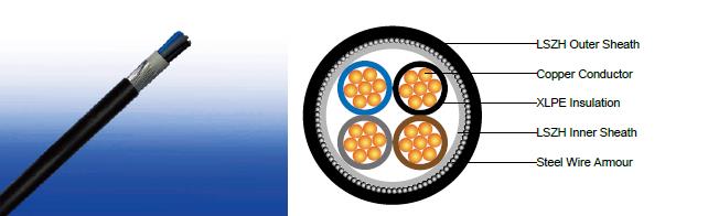
CABLE CONSTRUCTION
Conductor : The conductors shall be class 2 plain or metal-coated annealed copper in accordance with IEC
60228. Class 1 and class 5 conductor can be offered as option.
Insulation : Thermosetting XLPE material and thickness shall be as per IEC 60502-1.
Inner Covering : Thermoplastic halogen free compound ST8 as per IEC 60502-1.
Armouring : Steel wire armour.
Outer Sheath : Thermoplastic halogen free compound ST8 as per IEC 60502-1.
Outer Sheath Option : UV resistance, hydrocarbon resistance, oil resistance, anti-rodent and anti-termite
roperties can be offered as option.
COLOUR CODE
Insulation Colour |
2-core |
Brown and blue. |
3-core |
Brown, black and grey. |
|
4-core |
Blue, brown black and grey. |
|
5-core |
Green and yellow, blue, brown black, grey. |
|
Other colours can be offered upon request. |
||
Sheath Colour |
Black; other colours can be offered upon request. |
|
PHYSICAL AND THERMAL PROPERTIES
Maximum temperature range during operation : 90°C
Maximum short circuit temperature (5 Seconds) : 250°C
Minimum bending radius :
circular copper conductors : 6 × Overall Diameter
shaped copper conductors : 8 × Overall Diameter
CONSTRUCTION PARAMETERS
Conductor |
FTX400 1RZ1MZ1-R |
|||||||
No. of Cores × Cross-sectional Area |
Conductor Class |
Nominal Insulation Thickness |
Nominal Inner Covering Thickness |
Nominal Armour Wire Diameter |
Nominal Sheath Thickness |
Approx. Overall Diameter |
Approx. Weight |
|
No.×mm² |
|
mm |
mm |
mm |
mm |
mm |
kg/km |
|
2 cores |
||||||||
2×1.5 |
2 |
0.7 |
1.0 |
0.8 |
1.8 |
13.2 |
325 |
|
2×2.5 |
2 |
0.7 |
1.0 |
0.8 |
1.8 |
14.0 |
372 |
|
2×4 |
2 |
0.7 |
1.0 |
0.8 |
1.8 |
15.1 |
438 |
|
2×6 |
2 |
0.7 |
1.0 |
1.25 |
1.8 |
17.1 |
645 |
|
2×10 |
2 |
0.7 |
1.0 |
1.25 |
1.8 |
19.0 |
806 |
|
2×16 |
2 |
0.7 |
1.0 |
1.25 |
1.8 |
21.1 |
1015 |
|
2×25 |
2 |
0.9 |
1.0 |
1.6 |
1.8 |
25.2 |
1517 |
|
2×35 |
2 |
0.9 |
1.0 |
1.6 |
1.8 |
27.5 |
1830 |
|
2×50 |
2 |
1.0 |
1.0 |
1.6 |
1.9 |
30.8 |
2259 |
|
2×70 |
2 |
1.1 |
1.0 |
2.0 |
2.0 |
35.8 |
3182 |
|
2×95 |
2 |
1.1 |
1.2 |
2.0 |
2.1 |
40.2 |
4022 |
|
2×120 |
2 |
1.2 |
1.2 |
2.0 |
2.3 |
44.2 |
4810 |
|
2×150 |
2 |
1.4 |
1.2 |
2.5 |
2.4 |
49.3 |
6120 |
|
2×185 |
2 |
1.6 |
1.4 |
2.5 |
2.6 |
54.7 |
7375 |
|
2×240 |
2 |
1.7 |
1.4 |
2.5 |
2.7 |
60.5 |
9037 |
|
2×300 |
2 |
1.8 |
1.6 |
2.5 |
2.9 |
66.6 |
10871 |
|
2×400 |
2 |
2.0 |
1.6 |
2.5 |
3.1 |
73.7 |
13256 |
|
3 cores |
||||||||
3×1.5 |
2 |
0.7 |
1.0 |
0.8 |
1.8 |
13.6 |
368 |
|
3×2.5 |
2 |
0.7 |
1.0 |
0.8 |
1.8 |
14.5 |
427 |
|
3×4 |
2 |
0.7 |
1.0 |
0.8 |
1.8 |
15.7 |
514 |
|
3×6 |
2 |
0.7 |
1.0 |
1.25 |
1.8 |
17.8 |
752 |
|
3×10 |
2 |
0.7 |
1.0 |
1.25 |
1.8 |
19.8 |
965 |
|
3×16 |
2 |
0.7 |
1.0 |
1.25 |
1.8 |
22.1 |
1244 |
|
3×25 |
2 |
0.9 |
1.0 |
1.6 |
1.8 |
26.5 |
1872 |
|
3×35 |
2 |
0.9 |
1.0 |
1.6 |
1.8 |
29.0 |
2298 |
|
3×50 |
2 |
1.0 |
1.0 |
1.6 |
1.9 |
32.5 |
2876 |
|
3×70 |
2 |
1.1 |
1.0 |
2.0 |
2.1 |
38.0 |
4081 |
|
3×95 |
2 |
1.1 |
1.2 |
2.0 |
2.2 |
42.7 |
5227 |
|
3×120 |
2 |
1.2 |
1.2 |
2.0 |
2.3 |
46.8 |
6283 |
|
3×150 |
2 |
1.4 |
1.4 |
2.5 |
2.5 |
52.8 |
8045 |
|
3×185 |
2 |
1.6 |
1.4 |
2.5 |
2.7 |
58.1 |
9678 |
|
3×240 |
2 |
1.7 |
1.4 |
2.5 |
2.8 |
64.3 |
11998 |
|
3×300 |
2 |
1.8 |
1.6 |
2.5 |
3.0 |
70.8 |
14540 |
|
3×400 |
2 |
2 |
1.6 |
3.15 |
3.3 |
80.0 |
18919 |
|
3 cores + 1 core earth conductor |
||||||||
|
|
3 cores |
1 core |
|
|
|
|
|
3×16/10 |
2 |
0.7 |
0.7 |
1.0 |
1.6 |
1.8 |
23.5 |
1363 |
3×25/16 |
2 |
0.9 |
0.7 |
1.0 |
1.6 |
1.8 |
27.3 |
2054 |
3×35/16 |
2 |
0.9 |
0.7 |
1.0 |
1.6 |
1.9 |
30.1 |
2480 |
3×50/25 |
2 |
1.0 |
0.9 |
1.0 |
1.6 |
2.1 |
34.0 |
3167 |
3×70/35 |
2 |
1.1 |
0.9 |
1.2 |
2 |
2.2 |
39.9 |
4476 |
3×95/50 |
2 |
1.1 |
1.0 |
1.2 |
2 |
2.3 |
44.3 |
5757 |
3×120/70 |
2 |
1.2 |
1.1 |
1.2 |
2 |
2.5 |
48.8 |
7047 |
3×150/70 |
2 |
1.4 |
1.1 |
1.4 |
2.5 |
2.7 |
55.0 |
8812 |
3×185/95 |
2 |
1.6 |
1.1 |
1.4 |
2.5 |
2.8 |
60.4 |
10723 |
3×240/120 |
2 |
1.7 |
1.2 |
1.6 |
2.5 |
3.1 |
67.8 |
13326 |
3×300/150 |
2 |
1.8 |
1.4 |
1.6 |
2.5 |
3.2 |
73.8 |
16169 |
3×400/185 |
2 |
2.0 |
1.6 |
1.6 |
3.15 |
3.6 |
83.5 |
20955 |
4 cores |
||||||||
4×1.5 |
2 |
0.7 |
1.0 |
0.8 |
1.8 |
14.4 |
414 |
|
4×2.5 |
2 |
0.7 |
1.0 |
0.8 |
1.8 |
15.4 |
487 |
|
4×4 |
2 |
0.7 |
1.0 |
0.8 |
1.8 |
16.7 |
617 |
|
4×6 |
2 |
0.7 |
1.0 |
1.25 |
1.8 |
19.0 |
870 |
|
4×10 |
2 |
0.7 |
1.0 |
1.25 |
1.8 |
21.3 |
1136 |
|
4×16 |
2 |
0.7 |
1.0 |
1.6 |
1.8 |
24.5 |
1642 |
|
4×25 |
2 |
0.9 |
1.0 |
1.6 |
1.8 |
28.6 |
2254 |
|
4×35 |
2 |
0.9 |
1.0 |
1.6 |
1.9 |
31.6 |
2814 |
|
4×50 |
2 |
1.0 |
1.0 |
2.0 |
2.1 |
36.5 |
3837 |
|
4×70 |
2 |
1.1 |
1.2 |
2.0 |
2.2 |
41.9 |
5096 |
|
4×95 |
2 |
1.1 |
1.2 |
2.0 |
2.3 |
46.7 |
6499 |
|
4×120 |
2 |
1.2 |
1.4 |
2.5 |
2.5 |
52.9 |
8446 |
|
4×150 |
2 |
1.4 |
1.4 |
2.5 |
2.7 |
58.0 |
10039 |
|
4×185 |
2 |
1.6 |
1.4 |
2.5 |
2.8 |
63.7 |
12099 |
|
4×240 |
2 |
1.7 |
1.6 |
2.5 |
3.1 |
71.5 |
15261 |
|
4×300 |
2 |
1.8 |
1.6 |
2.5 |
3.2 |
78.0 |
18400 |
|
4×400 |
2 |
2.0 |
1.8 |
3.15 |
3.6 |
88.7 |
24037 |
|
5 cores |
||||||||
5x1.5 |
2 |
0.7 |
1.0 |
0.8 |
1.8 |
14.8 |
481 |
|
5×2.5 |
2 |
0.7 |
1.0 |
0.8 |
1.8 |
15.8 |
571 |
|
5×4 |
2 |
0.7 |
1.0 |
0.8 |
1.8 |
17.2 |
702 |
|
5×6 |
2 |
0.7 |
1.0 |
1.25 |
1.8 |
19.4 |
1020 |
|
5×10 |
2 |
0.7 |
1.0 |
1.25 |
1.8 |
21.6 |
1345 |
|
5×16 |
2 |
0.7 |
1.0 |
1.6 |
1.8 |
24.7 |
1944 |
|
5×25 |
2 |
0.9 |
1.0 |
1.6 |
1.9 |
29.0 |
2810 |
|
5×35 |
2 |
0.9 |
1.0 |
1.6 |
2.0 |
32.2 |
3398 |
|
ELECTRICAL PROPERTIES
Conductor operating temperature : 90°C
Air ambient temperature : 30°C
Ground ambient temperature : 20°C
Current-Carrying Capacities (Amp) according to BS 7671:2008 table 4E4A
Conductor cross-ectional area |
Ref. Method C (clipped direct) |
Ref. Method E (in free air or on a perforated cable tray etc. horizontal or vertical) |
Ref. Method D (direct in in groud or in ducting in groud. in or around buildings) |
|||
1 two-core cable, single-phase a.c. or d.c. |
1 three- or four-core cable, three-phase a.c. |
1 two-core cable, single-phase a.c. or d.c. |
1 three- or four-core cable, three-phase a.c. |
1 two-core cable, single-phase a.c. or d.c. |
1 three- or four-core cable, three-phase a.c. |
|
1 |
2 |
3 |
4 |
5 |
6 |
7 |
mm² |
A |
A |
A |
A |
A |
A |
1.5 |
27 |
23 |
29 |
25 |
25 |
21 |
2.5 |
36 |
31 |
39 |
33 |
33 |
28 |
4 |
49 |
42 |
52 |
44 |
43 |
36 |
6 |
62 |
53 |
66 |
56 |
53 |
44 |
10 |
85 |
73 |
90 |
78 |
71 |
58 |
16 |
110 |
94 |
115 |
99 |
91 |
75 |
25 |
146 |
124 |
152 |
131 |
116 |
96 |
35 |
180 |
154 |
188 |
162 |
139 |
115 |
50 |
219 |
187 |
228 |
197 |
164 |
135 |
70 |
279 |
238 |
291 |
251 |
203 |
167 |
95 |
338 |
289 |
354 |
304 |
239 |
197 |
120 |
392 |
335 |
410 |
353 |
271 |
223 |
150 |
451 |
386 |
472 |
406 |
306 |
251 |
185 |
515 |
441 |
539 |
463 |
343 |
281 |
240 |
607 |
520 |
636 |
546 |
395 |
324 |
300 |
698 |
599 |
732 |
628 |
446 |
365 |
400 |
787 |
673 |
847 |
728 |
- |
- |
Voltage Drop (Per Amp Per Meter) according to BS 7671:2008 table 4E4B
Conductor cross-sectional area |
Two-core cable, d.c. |
Two-core cable, single-phase a.c. |
Three- or four-core cable, three-phase a.c. |
||||
1 |
2 |
3 |
4 |
||||
mm² |
mV/A/m |
mV/A/m |
mV/A/m |
||||
1.5 |
31 |
31 |
27 |
||||
2.5 |
19 |
19 |
16 |
||||
4 |
12 |
12 |
10 |
||||
6 |
7.9 |
7.9 |
6.8 |
||||
10 |
4.7 |
4.7 |
4.0 |
||||
16 |
2.9 |
2.9 |
2.5 |
||||
|
|
r |
x |
z |
r |
x |
z |
25 |
1.85 |
1.85 |
0.160 |
1.90 |
1.60 |
0.140 |
1.65 |
35 |
1.35 |
1.35 |
0.155 |
1.35 |
1.15 |
0.135 |
1.15 |
50 |
0.98 |
0.99 |
0.155 |
1.00 |
0.86 |
0.135 |
0.87 |
70 |
0.67 |
0.67 |
0.150 |
0.69 |
0.59 |
0.130 |
0.60 |
95 |
0.49 |
0.50 |
0.150 |
0.52 |
0.43 |
0.130 |
0.45 |
120 |
0.39 |
0.40 |
0.145 |
0.42 |
0.34 |
0.130 |
0.37 |
150 |
0.31 |
0.32 |
0.145 |
0.35 |
0.38 |
0.125 |
0.30 |
185 |
0.25 |
0.26 |
0.145 |
0.29 |
0.22 |
0.125 |
0.26 |
240 |
0.195 |
0.200 |
0.140 |
0.24 |
0.175 |
0.125 |
0.21 |
300 |
0.155 |
0.160 |
0.140 |
0.21 |
0.140 |
0.120 |
0.185 |
400 |
0.120 |
0.130 |
0.140 |
0.190 |
0.115 |
0.120 |
0.165 |
Note :
r = conductor resistance at operating temperature
x = reactance
z = impedance