


| FIREGUARD Flame Retardant Cables | |||
![]() Fire retardant cable(Fireguard)
Fire retardant cable(Fireguard)
600/1000V XLPE Insulated, PVC Sheathed, Armoured Power Cables to IEC 60502 (Single Core)
FGD300 1RVMAV-R (CU/XLPE/PVC/AWA/PVC 600/1000V Class 2)
VDE Code: N2XRY
Application
The cables are mainly used in power stations, mass transit underground passenger systems, airports,
petrochemical plants, hotels, hospitals, and high-rise buildings.This product type is TUV approved.
Standards
Basic design to to IEC 60502-1
Approvals
TUV Certification (Z1 17 01 98200 004)
Fire Performance
| Flame Retardance (Single Vertical Wire Test) | IEC 60332-1 |
Voltage Rating
600/1000V
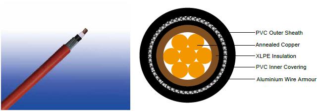
Cable Construction
Conductor :Annealed copper wire, stranded according to IEC 60228 class 2.
Insulation:XLPE according to IEC 60502-1.
Inner Covering:Extruded PVC or polymeric compound.
Armouring:Aluminium wire
Outer Sheath:Extruded PVC Type ST1/ST2 according to IEC 60502-1.
Outer Sheath Option:UV resistance, hydrocarbon resistance, oil resistance, anti rodent and anti termite
properties can be offered as option. Compliance to fire performance standard (IEC 60332-1, IEC 60332-3, UL
1581, UL 1666 etc) depends on the oxygen index of the PVC compound and the overall cable design. LSPVC can
also be provided upon request.
Colour Code
| Insulation Colour | Brown or blue, other colours can be offered upon request. |
Sheath Colour |
Black, other colours can be offered upon request. |
Mechanical and Electrical Properties
| Maximum temperature range during operation | 80°C (For ST1 Sheath); 90°C (For ST2 Sheath) |
||||||
Maximum short circuit temperature (5 Seconds) |
250°C |
||||||
|
|||||||
Minimum bending radius |
|
||||||
|
|||||||
Construction Parameters
| Conductor | FGD300 1RVMAV-R |
||||||
No. of Cores xCross Section |
Class of Conductor |
Nominal Insulation Thickness |
Nominal Inner Covering |
Nominal Armour Wire |
Nominal Sheath Thickness |
Approx. Overall |
Approx. Weight |
No.xmm2 |
|
mm |
mm |
mm |
mm |
mm |
kg/km |
1x1.5 |
2 |
0.7 |
1.0 |
0.8 |
1.8 |
10.2 |
150 |
1x2.5 |
2 |
0.7 |
1.0 |
0.8 |
1.8 |
10.6 |
169 |
1x4.0 |
2 |
0.7 |
1.0 |
0.8 |
1.8 |
11.2 |
196 |
1x6.0 |
2 |
0.7 |
1.0 |
0.8 |
1.8 |
11.7 |
228 |
1x10 |
2 |
0.7 |
1.0 |
0.8 |
1.8 |
12.7 |
290 |
1x16 |
2 |
0.7 |
1.0 |
0.8 |
1.8 |
13.7 |
372 |
1x25 |
2 |
0.9 |
1.0 |
0.8 |
1.8 |
15.4 |
507 |
1x35 |
2 |
0.9 |
1.0 |
1.25 |
1.8 |
17.5 |
681 |
1x50 |
2 |
1.0 |
1.0 |
1.25 |
1.8 |
19.0 |
848 |
1x70 |
2 |
1.1 |
1.0 |
1.25 |
1.8 |
21.0 |
1116 |
1x95 |
2 |
1.1 |
1.0 |
1.6 |
1.8 |
24.0 |
1511 |
1x120 |
2 |
1.2 |
1.0 |
1.6 |
1.8 |
25.8 |
1821 |
1x150 |
2 |
1.4 |
1.0 |
1.6 |
1.8 |
27.8 |
2165 |
1x185 |
2 |
1.6 |
1.0 |
1.6 |
1.8 |
30.4 |
2655 |
1x240 |
2 |
1.7 |
1.0 |
1.6 |
1.9 |
33.5 |
3352 |
1x300 |
2 |
1.8 |
1.0 |
2.0 |
2.0 |
37.5 |
4224 |
1x400 |
2 |
2.0 |
1.2 |
2.0 |
2.2 |
41.3 |
5263 |
1x500 |
2 |
2.2 |
1.2 |
2.0 |
2.3 |
44.2 |
7379 |
1x630 |
2 |
2.4 |
1.2 |
2.5 |
2.4 |
49.8 |
9611 |
1x800 |
2 |
2.6 |
1.4 |
2.5 |
2.6 |
55.3 |
11896 |
1x1000 |
2 |
2.8 |
1.4 |
2.5 |
2.7 |
60.4 |
14467 |
ELECTRICAL PROPERTIES
| Conductor Operating Temperature | 90°C |
Ambient Temperature |
30°C |
Current-Carrying Capacities (Amp) according to BS 7671: 2008 table 4E3A
Conductor cross-sectional area |
Reference |
Reference Method F (in free air or on a perforated cable tray, horizontal or vertical) |
|||||||||
Touching |
Touching |
Spaced by on cable diameter |
|||||||||
2 |
3 or 4 |
2 |
3 or 4 |
3 cables |
2 cables, d.c. |
2 cables, single-phase |
3 or 4 |
||||
Horizontal |
Vertical |
Horizontal |
Vertical |
Horizontal |
Vertical |
||||||
1 |
2 |
3 |
4 |
5 |
6 |
7 |
8 |
9 |
10 |
11 |
12 |
mm2 |
A |
A |
A |
A |
A |
A |
A |
A |
A |
A |
A |
50 |
237 |
220 |
253 |
232 |
222 |
284 |
270 |
282 |
266 |
288 |
266 |
70 |
303 |
277 |
322 |
293 |
285 |
356 |
349 |
357 |
337 |
358 |
331 |
95 |
367 |
333 |
389 |
352 |
346 |
446 |
426 |
436 |
412 |
425 |
393 |
120 |
425 |
383 |
449 |
405 |
402 |
519 |
497 |
504 |
477 |
485 |
449 |
150 |
488 |
437 |
516 |
462 |
463 |
600 |
575 |
566 |
539 |
549 |
510 |
185 |
557 |
496 |
587 |
524 |
529 |
688 |
660 |
643 |
614 |
618 |
574 |
240 |
656 |
579 |
689 |
612 |
625 |
815 |
782 |
749 |
714 |
715 |
666 |
300 |
755 |
662 |
792 |
700 |
720 |
943 |
906 |
842 |
805 |
810 |
755 |
400 |
853 |
717 |
899 |
767 |
815 |
1137 |
1094 |
929 |
889 |
848 |
797 |
500 |
962 |
791 |
1016 |
851 |
918 |
1314 |
1266 |
1032 |
989 |
923 |
871 |
630 |
1082 |
861 |
1146 |
935 |
1027 |
1528 |
1474 |
1139 |
1092 |
992 |
940 |
800 |
1170 |
904 |
1246 |
987 |
1119 |
1809 |
1744 |
1204 |
1155 |
1042 |
978 |
1000 |
1261 |
961 |
1345 |
1055 |
1214 |
2100 |
2026 |
1289 |
1238 |
1110 |
1041 |
Voltage Drop (Per Amp Per Meter) according to BS 7671: 2008 table 4E3B
Nominal Cross Section Area |
2 cables d.c. |
Ref. Methods C&F(clipped direct, on trays or in free air) |
||||||||||||||
2 cables, single-phase a.c. |
3 or 4 cables, three-phase a.c. |
|||||||||||||||
Touching |
Spaced* |
Trefoil and touching |
Flat and touching |
Flat and spaced* |
||||||||||||
1 |
2 |
3 |
4 |
5 |
6 |
7 |
||||||||||
mm2 |
mV/A/m |
mV/A/m |
mV/A/m |
mV/A/m |
mV/A/m |
mV/A/m |
||||||||||
|
|
r |
x |
z |
r |
x |
z |
r |
x |
z |
r |
x |
z |
r |
x |
z |
50 |
0.98 |
0.99 |
0.21 |
1.0 |
0.98 |
0.29 |
1.0 |
0.86 |
0.18 |
0.87 |
0.64 |
0.25 |
0.88 |
0.84 |
0.33 |
0.9 |
70 |
0.67 |
0.68 |
0.20 |
0.71 |
0.69 |
0.29 |
0.75 |
0.59 |
0.170 |
0.62 |
0.60 |
0.25 |
0.65 |
0.62 |
0.32 |
0.70 |
95 |
0.49 |
0.51 |
0.195 |
0.55 |
0.53 |
0.28 |
0.60 |
0.44 |
0.170 |
0.47 |
0.46 |
0.24 |
0.52 |
0.49 |
0.31 |
0.58 |
120 |
0.39 |
0.41 |
0.190 |
0.45 |
0.43 |
0.27 |
0.51 |
0.35 |
0.165 |
0.39 |
0.38 |
0.24 |
0.44 |
0.41 |
0.30 |
0.51 |
150 |
0.31 |
0.33 |
0.185 |
0.38 |
0.36 |
0.27 |
0.45 |
0.29 |
0.160 |
0.33 |
0.31 |
0.23 |
0.39 |
0.34 |
0.29 |
0.45 |
185 |
0.25 |
0.27 |
0.185 |
0.33 |
0.30 |
0.26 |
0.40 |
0.23 |
0.160 |
0.28 |
0.26 |
0.23 |
0.34 |
0.29 |
0.29 |
0.41 |
240 |
0.195 |
0.21 |
0.180 |
0.28 |
0.24 |
0.26 |
0.35 |
0.180 |
0.155 |
0.24 |
0.21 |
0.22 |
0.30 |
0.24 |
0.28 |
0.37 |
300 |
0.155 |
0.17 |
0.175 |
0.25 |
0.195 |
0.25 |
0.32 |
0.145 |
0.150 |
0.21 |
0.170 |
0.22 |
0.28 |
0.20 |
0.27 |
0.34 |
400 |
0.115 |
0.145 |
0.170 |
0.22 |
0.180 |
0.24 |
0.30 |
0.125 |
0.150 |
0.195 |
0.160 |
0.21 |
0.27 |
0.20 |
0.27 |
0.33 |
500 |
0.093 |
0.125 |
0.170 |
0.21 |
0.165 |
0.24 |
0.29 |
0.105 |
0.145 |
0.180 |
0.145 |
0.20 |
0.25 |
0.190 |
0.24 |
0.31 |
630 |
0.073 |
0.105 |
0.165 |
0.195 |
0.150 |
0.23 |
0.27 |
0.092 |
0.145 |
0.170 |
0.135 |
0.195 |
0.24 |
0.175 |
0.23 |
0.29 |
800 |
0.056 |
0.090 |
0.160 |
0.190 |
0.145 |
0.23 |
0.27 |
0.086 |
0.140 |
0.165 |
0.130 |
0.180 |
0.23 |
0.175 |
0.195 |
0.26 |
1000 |
0.045 |
0.092 |
0.155 |
0.180 |
0.140 |
0.21 |
0.25 |
0.080 |
0.135 |
0.155 |
0.125 |
0.170 |
0.21 |
0.165 |
0.180 |
0.24 |
Note: *Spacings larger than one cable diameter will result in a large voltage drop.
r = conductor resistance at operating temperature
x = reactance
z = impedance