


| FIREGUARD Flame Retardant Cables | |||
![]() Fire retardant cable(Fireguard)
Fire retardant cable(Fireguard)
450/750V PVC Insulated, Non-sheathed Power Cables (Single Core)
FGD100 07V-U/R/K (CU/PVC 450/750V Class 1/2/5)
BS Code : 6491X
HAR Code : H07V-U, H07V-R, H07V-K
APPLICATION
This cables are mainly used in power stations, mass transit underground passenger systems, airports,
petrochemical plants, hotels, hospitals, and high-rise buildings. This product type is CE and TUV approved.
STANDARDS
Basic design to BS EN 50525-2-31(formerly BS 6004:2000)
FIRE PERFORMANCE
| Flame Retardance (Single Vertical Wire Test) | EN 60332-1-2 |
VOLTAGE RATING
450/750V
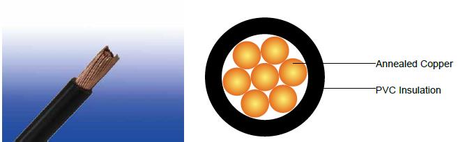
CABLE CONSTRUCTION
Conductor
|
H05V-U |
Class 1 solid copper conductor to BS EN 60228. |
H05V-R |
Class 2 stranded copper conductor to BS EN 60228. |
|
H05V-K |
Class 5 stranded copper conductor to BS EN 60228. |
|
Insulation |
PVC Type TI 1 according to BS EN 50363-3 |
|
COLOUR CODE
Black, Blue, Brown, Grey, Orange, Pink, Red, Turquoise, Violet, White, Green and Yellow.
PHYSICAL AND THERMAL PROPERTIES
| Maximum temperature range during operation (PVC) | 70°C |
|
Maximum short circuit temperature (5 Seconds) |
160°C |
|
Minimum bending radius |
Up to 8mm² |
4 x overall diameter |
|
8mm² to 12mm² |
5 x overall diameter |
|
Above 12mm² |
6 x overall diameter |
CONSTRUCTION PARAMETERS
Conductor |
FGD100 07V-U/R/K |
|||
No. of Cores x Cross Section |
Class of Conductor |
Nominal Insulation Thickness |
Maximum Overall Diameter |
Approx. Weight |
No.xmm² |
|
mm |
mm |
kg/km |
1x1.5 |
1 |
0.7 |
3.2 |
21 |
1x2.5 |
1 |
0.8 |
3.9 |
33 |
1x4.0 |
1 |
0.8 |
4.4 |
49 |
1x6.0 |
1 |
0.8 |
5.0 |
69 |
1x10 |
1 |
1.0 |
6.4 |
115 |
1x1.5 |
2 |
0.7 |
3.3 |
23 |
1x2.5 |
2 |
0.8 |
4.0 |
35 |
1x4.0 |
2 |
0.8 |
4.6 |
51 |
1x6.0 |
2 |
0.8 |
5.2 |
71 |
1x10 |
2 |
1.0 |
6.7 |
120 |
1x16 |
2 |
1.0 |
7.8 |
170 |
1x25 |
2 |
1.2 |
9.7 |
260 |
1x35 |
2 |
1.2 |
10.9 |
350 |
1x50 |
2 |
1.4 |
12.8 |
480 |
1x70 |
2 |
1.4 |
14.6 |
680 |
1x95 |
2 |
1.6 |
17.1 |
930 |
1x120 |
2 |
1.6 |
18.8 |
1160 |
1x150 |
2 |
1.8 |
20.9 |
1430 |
1x185 |
2 |
2.0 |
23.3 |
1780 |
1x240 |
2 |
2.2 |
26.6 |
2360 |
1x300 |
2 |
2.4 |
29.6 |
2940 |
1x400 |
2 |
2.6 |
33.2 |
3740 |
1x500 |
2 |
2.8 |
36.9 |
4950 |
1x630 |
2 |
2.8 |
41.1 |
6300 |
1x800 |
2 |
2.8 |
45.7 |
8610 |
1x1000 |
2 |
3.0 |
51.0 |
10820 |
1x1.5 |
5 |
0.7 |
3.4 |
20 |
1x2.5 |
5 |
0.8 |
4.1 |
31 |
1x4.0 |
5 |
0.8 |
4.8 |
48 |
1x6.0 |
5 |
0.8 |
5.3 |
69 |
1x10 |
5 |
1.0 |
6.8 |
121 |
1x16 |
5 |
1.0 |
8.1 |
211 |
1x25 |
5 |
1.2 |
10.2 |
303 |
1x35 |
5 |
1.2 |
11.7 |
417 |
1x50 |
5 |
1.4 |
13.9 |
539 |
1x70 |
5 |
1.4 |
16.0 |
730 |
1x95 |
5 |
1.6 |
18.2 |
900 |
1x120 |
5 |
1.6 |
20.2 |
1135 |
1x150 |
5 |
1.8 |
22.5 |
1410 |
1x185 |
5 |
2.0 |
24.9 |
1845 |
1x240 |
5 |
2.2 |
28.4 |
2270 |
ELECTRICAL PROPERTIES
| Conductor Operating Temperature | 70°C |
Ambient Temperature |
30°C |
Current-Carrying Capacities (Amp) according to BS 7671:2008 table 4D1A
Conductor cross- sectional area |
Reference Method A (enclosed in conduit in thermally insulating wall etc) |
Reference Method B (enclosed in conduit on a wall or in trunking etc) |
Reference Method C (clipped direct) |
Reference Method F (in free air or on a perforated cable tray horizontal or vertical etc) |
|||||||
Touching |
Spaced by one cable diameter |
||||||||||
2 cables, single-phase a.c. or d.c. |
3 or 4 cables, three -phase a.c. |
2 cables, single-phase a.c. or d.c |
3 or 4 cables, three-phase a.c. |
2 cables, single-phase a.c. or d.c. flat and touching |
3 or 4 cables, three-phase a.c. flat and touching or trefoil |
2 cables, single-phase a.c. or d.c. flat |
3 cables, three-phase a.c. flat |
3 cables, three-phase a.c. trefoil |
2 cables, single-phase a.c. or d.c. or 3 cables three- phase a.c. flat |
||
Horizontal |
Vertical |
||||||||||
1 |
2 |
3 |
4 |
5 |
6 |
7 |
8 |
9 |
10 |
11 |
12 |
mm² |
A |
A |
A |
A |
A |
A |
A |
A |
A |
A |
A |
1.5 |
14.5 |
13.5 |
17.5 |
15.5 |
20 |
18 |
- |
- |
- |
- |
- |
2.5 |
20 |
18 |
24 |
21 |
27 |
25 |
- |
- |
- |
- |
- |
4.0 |
26 |
24 |
32 |
28 |
37 |
33 |
- |
- |
- |
- |
- |
6.0 |
34 |
31 |
41 |
36 |
47 |
43 |
- |
- |
- |
- |
- |
10 |
46 |
42 |
57 |
50 |
65 |
59 |
- |
- |
- |
- |
- |
16 |
61 |
56 |
76 |
68 |
87 |
79 |
- |
- |
- |
- |
- |
25 |
80 |
73 |
101 |
89 |
114 |
104 |
131 |
114 |
110 |
146 |
130 |
35 |
99 |
89 |
125 |
110 |
141 |
129 |
162 |
143 |
137 |
181 |
162 |
50 |
119 |
108 |
151 |
134 |
182 |
167 |
196 |
174 |
167 |
219 |
197 |
70 |
151 |
136 |
192 |
171 |
234 |
214 |
251 |
225 |
216 |
281 |
254 |
95 |
182 |
164 |
232 |
207 |
284 |
261 |
304 |
275 |
264 |
341 |
311 |
120 |
210 |
188 |
269 |
239 |
330 |
303 |
352 |
321 |
308 |
396 |
362 |
150 |
240 |
216 |
300 |
262 |
381 |
349 |
406 |
372 |
356 |
456 |
419 |
185 |
273 |
245 |
341 |
296 |
436 |
400 |
463 |
427 |
409 |
521 |
480 |
240 |
321 |
286 |
400 |
346 |
515 |
472 |
546 |
507 |
485 |
615 |
569 |
300 |
367 |
328 |
458 |
394 |
594 |
545 |
629 |
587 |
561 |
709 |
659 |
400 |
- |
- |
546 |
467 |
694 |
634 |
754 |
689 |
656 |
852 |
795 |
500 |
- |
- |
626 |
533 |
792 |
723 |
868 |
789 |
749 |
982 |
920 |
630 |
- |
- |
720 |
611 |
904 |
826 |
1005 |
905 |
855 |
1138 |
1070 |
800 |
- |
- |
- |
- |
1030 |
943 |
1086 |
1020 |
971 |
1265 |
1188 |
1000 |
- |
- |
- |
- |
1154 |
1058 |
1216 |
1149 |
1079 |
1420 |
1337 |
Voltage Drop (Per Amp Per Meter) according to BS 7671:2008 table 4D1B
Nominal Cross Section Area |
2 cables d.c. |
2 cables, single-phase a.c. |
3 or 4 cables, three-phase a.c. |
|||||||||||||||||||
Ref. Methods A and B (enclosed in conduit or trunking) |
Ref. Methods C & F(clipped direct, on trays or in free air) |
Ref. Methods A & B (enclosed in conduit or trunking |
Ref. Methods C & F (clipped direct, on trays or in free air) |
|||||||||||||||||||
Cables touching |
Cables spaced* |
Cables touching, Trefoil |
Cables touching, Flat |
Cables spaced*, Flat |
||||||||||||||||||
1 |
2 |
3 |
4 |
5 |
6 |
7 |
8 |
9 |
||||||||||||||
mm² |
mV/A/m |
mV/A/m |
mV/A/m |
mV/A/m |
mV/A/m |
mV/A/m |
mV/A/m |
mV/A/m |
||||||||||||||
1.5 |
29 |
29 |
29 |
29 |
25 |
25 |
25 |
25 |
||||||||||||||
2.5 |
18 |
18 |
18 |
18 |
15 |
15 |
15 |
15 |
||||||||||||||
4.0 |
11 |
11 |
11 |
11 |
9.5 |
9.5 |
9,5 |
9.5 |
||||||||||||||
6.0 |
7.3 |
7.3 |
7.3 |
7.3 |
6.4 |
6.4 |
6.4 |
6.4 |
||||||||||||||
10 |
4.4 |
4.4 |
4.4 |
4.4 |
3.8 |
3.8 |
3.8 |
3.8 |
||||||||||||||
16 |
2.8 |
2.8 |
2.8 |
2.8 |
2.4 |
2.4 |
2.4 |
2.4 |
||||||||||||||
|
|
r |
x |
z |
r |
x |
z |
r |
x |
z |
r |
x |
z |
r |
x |
z |
r |
x |
z |
r |
x |
z |
25 |
1.75 |
1.80 |
0.33 |
1.80 |
1.75 |
0.20 |
1.75 |
1.75 |
0.29 |
1.80 |
1.50 |
0.29 |
1.55 |
1.50 |
0.175 |
1.50 |
1.50 |
0.25 |
1.55 |
1.50 |
0.32 |
1.55 |
35 |
1.25 |
1.30 |
0.31 |
1.30 |
1.25 |
0.195 |
1.25 |
1.25 |
0.28 |
1.30 |
1.10 |
0.27 |
1.10 |
1.10 |
0.170 |
1.10 |
1.10 |
0.24 |
1.10 |
1.10 |
0.32 |
1.15 |
50 |
0.93 |
0.95 |
0.3 |
1.0 |
0.93 |
0.19 |
0.95 |
0.93 |
0.28 |
0.97 |
0.81 |
0.26 |
0.85 |
0.8 |
0.165 |
0.82 |
0.8 |
0.24 |
0.84 |
0.8 |
0.32 |
0.86 |
70 |
0.63 |
0.65 |
0.29 |
0.72 |
0.63 |
0.185 |
0.66 |
0.63 |
0.27 |
0.69 |
0.56 |
0.25 |
0.61 |
0.55 |
0.16 |
0.57 |
0.55 |
0.24 |
0.6 |
0.55 |
0.31 |
0.63 |
95 |
0.46 |
0.49 |
0.28 |
0.56 |
0.47 |
0.18 |
0.5 |
0.47 |
0.27 |
0.54 |
0.42 |
0.24 |
0.48 |
0.41 |
0.155 |
0.43 |
0.41 |
0.23 |
0.47 |
0.4 |
0.31 |
0.51 |
120 |
0.36 |
0.39 |
0.27 |
0.47 |
0.37 |
0.175 |
0.41 |
0.37 |
0.26 |
0.45 |
0.33 |
0.23 |
0.41 |
0.32 |
0.15 |
0.36 |
0.32 |
0.23 |
0.4 |
0.32 |
0.3 |
0.44 |
150 |
0.29 |
0.31 |
0.27 |
0.41 |
0.3 |
0.175 |
0.34 |
0.29 |
0.26 |
0.39 |
0.27 |
0.23 |
0.36 |
0.26 |
0.15 |
0.3 |
0.26 |
0.23 |
0.34 |
0.26 |
0.3 |
0.4 |
185 |
0.23 |
0.25 |
0.27 |
0.37 |
0.24 |
0.17 |
0.29 |
0.24 |
0.26 |
0.35 |
0.22 |
0.23 |
0.32 |
0.21 |
0.145 |
0.26 |
0.21 |
0.22 |
0.31 |
0.21 |
0.3 |
0.36 |
240 |
0.18 |
0.195 |
0.26 |
0.33 |
0.185 |
0.165 |
0.25 |
0.185 |
0.25 |
0.31 |
0.17 |
0.23 |
0.29 |
0.16 |
0.145 |
0.22 |
0.16 |
0.22 |
0.27 |
0.16 |
0.29 |
0.34 |
300 |
0.145 |
0.16 |
0.26 |
0.31 |
0.15 |
0.165 |
0.22 |
0.15 |
0.25 |
0.29 |
0.14 |
0.23 |
0.27 |
0.13 |
0.14 |
0.19 |
0.13 |
0.22 |
0.25 |
0.13 |
0.29 |
0.32 |
400 |
0.105 |
0.13 |
0.26 |
0.29 |
0.12 |
0.16 |
0.2 |
0.115 |
0.25 |
0.27 |
0.12 |
0.22 |
0.25 |
0.105 |
0.14 |
0.175 |
0.105 |
0.21 |
0.24 |
0.1 |
0.29 |
0.31 |
500 |
0.086 |
0.11 |
0.26 |
0.28 |
0.098 |
0.155 |
0.185 |
0.093 |
0.24 |
0.26 |
0.1 |
0.22 |
0.25 |
0.086 |
0.135 |
0.16 |
0.086 |
0.21 |
0.23 |
0.081 |
0.29 |
0.3 |
630 |
0.068 |
0.094 |
0.25 |
0.27 |
0.081 |
0.155 |
0.175 |
0.076 |
0.24 |
0.25 |
0.08 |
0.22 |
0.24 |
0.072 |
0.135 |
0.15 |
0.072 |
0.21 |
0.22 |
0.066 |
0.28 |
0.29 |
800 |
0.053 |
- |
- |
- |
0.068 |
0.15 |
0.165 |
0.061 |
0.24 |
0.25 |
- |
- |
- |
0.06 |
0.13 |
0.145 |
0.06 |
0.21 |
0.22 |
0.053 |
0.28 |
0.29 |
1000 |
0.042 |
- |
- |
- |
0.059 |
0.15 |
0.16 |
0.05 |
0.24 |
0.24 |
- |
- |
- |
0.052 |
0.13 |
0.14 |
0.052 |
0.2 |
0.21 |
0.044 |
0.28 |
0.28 |
Note: *Spacings larger than one cable diameter will result in a large voltage drop.
r = conductor resistance at operating temperature
x = reactance
z = impedance