


| FIREGUARD Flame Retardant Cables | |||
![]() Fire retardant cable(Fireguard)
Fire retardant cable(Fireguard)
600/1000V XLPE Insulated, PVC Sheathed, Unarmoured Power Cables to BS 7889 (Single Core)
FGD300 1RV-R (CU/XLPE/PVC 600/1000V Class 2)
BS Code: 6181X
Application
BS 7889 CU/XLPE/PVC are mainly use in fixed installations in industrial areas, buildings and similar applications
but not for burial in the ground, either directly or in ducts.
Standards
Basic design to to BS 7889:2012
Fire Performance
| Flame Retardance (Single Vertical Wire Test) | BS EN 60332-1-2 |
Voltage Rating
600/1000V
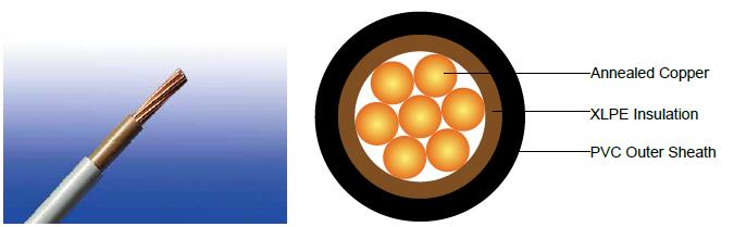
Cable Construction
Conductor:Annealed copper conductor, class 5 according to BS EN 60228.
Insulation:XLPE type GP8 according to BS 7655-1.3.
Inner Covering Option:The optional inner covering, where used, shall consist of an extruded layer of synthetic
polymeric material. It shall surround the single core and the laid-up two, three, four or five cores, giving the
assembly a practically circular shape.
Outer Sheath:PVC Type 9 according to BS 7655-4.2.
Outer Sheath Option:UV resistance, hydrocarbon resistance, oil resistance, anti rodent and anti termite
properties can be offered as option. Compliance to fire performance standard (IEC 60332-1, IEC 60332-3, UL
1581, UL 1666 etc) depends on the oxygen index of the PVC compound and the overall cable design. LSPVC can
also be provided upon request.
Colour Code
Insulation Colour :Brown or blue
Sheath Colour:Black, other colours can be offered upon request.
Mechanical and Electrical Properties
| Maximum temperature range during operation (XLPE) | 90°C |
Maximum short circuit temperature (5 Seconds) |
250°C |
Minimum bending radius |
Circular copper conductor (OD≤25mm): 4 x Overall Diameter |
|
Circular copper conductor (OD>25mm): 6 x Overall Diameter |
|
Shaped copper conductor: 8 x Overall Diameter |
Construction Parameters
| Conductor | FGD300 1RV-R |
||||
No. of Cores xCross Section |
Class of Conductor |
Nominal Insulation Thickness |
Nominal Sheath Thickness |
Nominal Overall Diameter |
Approx.Weight |
No.xmm2 |
|
mm |
mm |
mm |
kg/km |
1x1.5 |
2 |
0.7 |
1.4 |
6.1 |
36 |
1x2.5 |
2 |
0.7 |
1.4 |
6.8 |
52 |
1x4.0 |
2 |
0.7 |
1.4 |
7.4 |
76 |
1x6.0 |
2 |
0.7 |
1.4 |
8.2 |
100 |
1x10 |
2 |
0.7 |
1.4 |
9.2 |
160 |
1x16 |
2 |
0.7 |
1.4 |
10.7 |
230 |
1x25 |
2 |
0.9 |
1.4 |
12.5 |
340 |
1x35 |
2 |
0.9 |
1.4 |
13.5 |
440 |
1x50 |
2 |
1 |
1.4 |
13.7 |
541 |
1x70 |
2 |
1.1 |
1.4 |
15.8 |
749 |
1x95 |
2 |
1.1 |
1.5 |
17.5 |
1000 |
1x120 |
2 |
1.2 |
1.5 |
19.3 |
1241 |
1x150 |
2 |
1.4 |
1.6 |
21.5 |
1523 |
1x185 |
2 |
1.6 |
1.6 |
24.7 |
1942 |
1x240 |
2 |
1.7 |
1.7 |
27.7 |
2514 |
1x300 |
2 |
1.8 |
1.8 |
30.6 |
3125 |
1x400 |
2 |
2 |
1.9 |
34.2 |
3967 |
1x500 |
2 |
2.2 |
2 |
38 |
5063 |
1x630 |
2 |
2.4 |
2.2 |
42.9 |
6491 |
1x800 |
2 |
2.6 |
2.3 |
46 |
8075 |
1x1000 |
2 |
2.8 |
2.4 |
63 |
9860 |
ELECTRICAL PROPERTIES
Conductor Operating Temperature :70°C
Ambient Temperature:30°C
Current-Carrying Capacities (Amp) according to BS 7671:2008 table 4E1A
Conductor cross-sectional area |
Reference Method A (enclosed in conduit in thermally insulating wall etc) |
Reference Method B (enclosed in conduit on a wall or in trunking etc) |
Reference Method C (clipped direct) |
Reference Method F (in free air or on a perforated cable tray horizontal or vertical etc) |
Reference Method G (in free air) Spaced by one cable diameter |
||||||
2 cables, single-phase a.c. or d.c. |
3 or 4 cables, three-phase a.c. |
2 cables, single-phase a.c. or d.c |
3 or 4 cables, three-phase a.c. |
2 cables, single-phase a.c. or d.c. flat and touching |
3 or 4 cables, three-phase a.c. flat and touching or trefoil |
2 cables, single-phase a.c. or d.c. flat |
3 cables, three-phase a.c. flat |
3 cables, three-phase a.c. trefoil |
2 cables, single-phase a.c. or d.c. or 3 cables three-phase a.c. flat |
||
Horizontal |
Vertical |
||||||||||
1 |
2 |
3 |
4 |
5 |
6 |
7 |
8 |
9 |
10 |
11 |
12 |
mm² |
A |
A |
A |
A |
A |
A |
A |
A |
A |
A |
A |
1.5 |
19 |
17 |
23 |
20 |
25 |
23 |
- |
- |
- |
- |
- |
2.5 |
26 |
23 |
31 |
28 |
34 |
31 |
- |
- |
- |
- |
- |
4 |
35 |
31 |
42 |
37 |
46 |
41 |
- |
- |
- |
- |
- |
6 |
45 |
40 |
54 |
48 |
59 |
54 |
- |
- |
- |
- |
- |
10 |
61 |
54 |
75 |
66 |
81 |
74 |
- |
- |
- |
- |
- |
16 |
81 |
73 |
100 |
88 |
109 |
99 |
- |
- |
- |
- |
- |
25 |
106 |
95 |
133 |
117 |
143 |
130 |
161 |
141 |
135 |
182 |
161 |
35 |
131 |
117 |
164 |
144 |
176 |
161 |
200 |
176 |
169 |
226 |
201 |
50 |
158 |
141 |
198 |
175 |
228 |
209 |
242 |
216 |
207 |
275 |
246 |
70 |
200 |
179 |
253 |
222 |
293 |
268 |
310 |
279 |
268 |
353 |
318 |
95 |
241 |
216 |
306 |
269 |
355 |
326 |
377 |
342 |
328 |
430 |
389 |
120 |
278 |
249 |
354 |
312 |
413 |
379 |
437 |
400 |
383 |
500 |
454 |
150 |
318 |
285 |
393 |
342 |
476 |
436 |
504 |
464 |
444 |
577 |
527 |
185 |
362 |
324 |
449 |
384 |
545 |
500 |
575 |
533 |
510 |
661 |
605 |
240 |
424 |
380 |
528 |
450 |
644 |
590 |
679 |
634 |
607 |
781 |
719 |
300 |
486 |
435 |
603 |
514 |
743 |
681 |
783 |
736 |
703 |
902 |
833 |
400 |
- |
- |
683 |
584 |
868 |
793 |
940 |
868 |
823 |
1085 |
1008 |
500 |
- |
- |
783 |
666 |
990 |
904 |
1083 |
998 |
946 |
1253 |
1169 |
630 |
- |
- |
900 |
764 |
113 |
1033 |
1254 |
1151 |
1088 |
1454 |
1362 |
800 |
- |
- |
- |
- |
1288 |
1179 |
1358 |
1275 |
1214 |
1581 |
1485 |
1000 |
- |
- |
- |
- |
1443 |
1323 |
1520 |
1436 |
1349 |
1775 |
1671 |
Voltage Drop (Per Amp Per Meter) according to BS 7671:2008 table 4E1B
Nominal Cross Section Area |
2 |
2 cables, single-phase a.c. |
3 or 4 cables, three-phase a.c. |
|||||||||||||||
Ref. Methods A and B (enclosed in conduit or trunking) |
Ref. Methods C, F & G(clipped direct, on trays or in free air) |
Ref. Methods A & B (enclosed in conduit or trunking |
Ref. Methods C, F & G (clipped direct, on trays or in free air) |
|||||||||||||||
1 |
2 |
3 |
Cables touching 4 |
Cables spaced* 5 |
6 |
7 |
||||||||||||
mm² |
mV/A/m |
mV/A/m |
mV/A/m |
mV/A/m |
mV/A/m |
mV/A/m |
||||||||||||
1.5 |
31 |
|
31 |
|
|
27 |
|
|
27 |
|
|
27 |
|
|
27 |
|
||
2.5 |
19 |
|
19 |
|
|
16 |
|
|
16 |
|
|
16 |
|
|
16 |
|
||
4 |
33 |
|
12 |
|
|
10 |
|
|
10 |
|
|
10 |
|
|
10 |
|
||
6 |
7.8 |
|
7.9 |
|
|
6.8 |
|
|
6.8 |
|
|
6.8 |
|
|
6.8 |
|
||
10 |
4.7 |
|
4.7 |
|
|
4.7 |
|
|
4 |
|
|
4 |
|
|
4 |
|
||
16 |
2.9 |
|
2.9 |
|
|
2.9 |
|
|
2.5 |
|
|
2.5 |
|
|
2.5 |
|
||
|
|
r |
x |
z |
r |
x |
z |
r |
x |
z |
r |
x |
z |
r |
x |
z |
||
25 |
1.85 |
1.6 |
0.31 |
1.9 |
1.85 |
0.19 |
1.85 |
1.6 |
0.27 |
1.65 |
1.6 |
0.165 |
1.6 |
1.6 |
0.19 |
1.6 |
||
35 |
1.35 |
1.35 |
0.29 |
1.35 |
1.35 |
0.18 |
1.35 |
1.15 |
0.25 |
1.15 |
1.15 |
0.155 |
1.5 |
1.15 |
0.18 |
1.15 |
||
50 |
0.99 |
1 |
0.29 |
1.05 |
0.99 |
0.18 |
1 |
0.87 |
0.25 |
0.9 |
0.86 |
0.155 |
0.87 |
0.86 |
0.18 |
0.87 |
||
70 |
0.68 |
0.7 |
0.28 |
0.75 |
0.68 |
0.175 |
0.71 |
0.6 |
0.24 |
0.65 |
0.59 |
0.15 |
0.61 |
0.59 |
0.175 |
0.62 |
||
95 |
0.49 |
0.51 |
0.27 |
0.58 |
0.49 |
0.17 |
0.52 |
0.44 |
0.23 |
0.5 |
0.43 |
0.145 |
0.45 |
0.43 |
0.17 |
0.46 |
||
120 |
0.39 |
0.41 |
0.26 |
0.48 |
0.39 |
0.165 |
0.43 |
0.35 |
0.23 |
0.42 |
0.34 |
0.14 |
0.37 |
0.34 |
0.165 |
0.38 |
||
150 |
0.32 |
0.33 |
0.26 |
0.43 |
0.32 |
0.165 |
0.36 |
0.29 |
0.23 |
0.37 |
0.28 |
0.14 |
0.31 |
0.28 |
0.165 |
0.32 |
||
185 |
0.25 |
0.27 |
0.26 |
0.37 |
0.26 |
0.165 |
0.3 |
0.23 |
0.23 |
0.32 |
0.22 |
0.14 |
0.26 |
0.22 |
0.165 |
0.28 |
||
240 |
0.19 |
0.21 |
0.26 |
0.33 |
0.2 |
0.16 |
0.25 |
0.185 |
0.22 |
0.29 |
0.17 |
0.14 |
0.22 |
0.17 |
0.165 |
0.24 |
||
300 |
0.155 |
0.175 |
0.25 |
0.31 |
0.16 |
0.16 |
0.22 |
0.15 |
0.22 |
0.27 |
0.14 |
0.14 |
0.195 |
0.135 |
0.16 |
0.21 |
||
400 |
0.12 |
0.14 |
0.25 |
0.29 |
0.13 |
0.155 |
0.2 |
0.125 |
0.22 |
0.25 |
0.11 |
0.135 |
0.175 |
0.11 |
0.16 |
0.195 |
||
500 |
0.093 |
0.12 |
0.25 |
0.28 |
0.105 |
0.155 |
0.185 |
0.1 |
0.22 |
0.24 |
0.09 |
0.135 |
0.16 |
0.088 |
0.16 |
0.18 |
||
630 |
0.072 |
0.1 |
0.25 |
0.27 |
0.086 |
0.155 |
0.175 |
0.088 |
0.21 |
0.23 |
0.074 |
0.135 |
0.15 |
0.071 |
0.16 |
0.17 |
||
800 |
0.056 |
- |
- |
- |
0.072 |
0.15 |
0.17 |
- |
- |
- |
0.062 |
0.13 |
0.145 |
0.059 |
0.155 |
0.165 |
||
1000 |
0.045 |
- |
- |
- |
0.063 |
0.15 |
0.165 |
- |
- |
- |
0.055 |
0.13 |
0.14 |
0.05 |
0.155 |
0.165 |
||
Note: *Spacings larger than one cable diameter will result in a large voltage drop.
r = conductor resistance at operating temperature
x = reactance
z = impedance