


Fire Resisting Cable |
||||||||||
![]() Fire Resisting Cables
Fire Resisting Cables
600/1000V Mica+XLPE Insulated, LSZH Sheathed Power Cables to BS 8573 (2-5 Cores)
FFX400 1mRZ1-R (CU/MGT+XLPE/LSZH 600/1000V Class 2)
APPLICATION
The cables are mainly used in power stations, mass transit underground passenger systems, airports,
petrochemical plants, hotels, hospitals and high-rise buildings.
STANDARDS
Basic design adapted from BS 8573:2012
FIRE PERFORMANCE
| Circuit Integrity | IEC 60331-21; EN 6387; BS 8491 |
Flame Retardance (Single vertical wire or cable test) |
IEC 60332-1-2; EN 60332-1-2 |
Reduced fire Propagation (Vertically-mounted bundled wires & cables test) |
IEC 60332-3-24; EN 60332-3-24 |
Halogen Free |
IEC 60754-1; EN 50267-2-1 |
No Corrosive Gas Emission |
IEC 60754-2; EN 50267-2-2 |
Minimum Smoke Emission |
IEC 61034-2; EN 61034-2 |
VOLTAGE RATING
600/1000V
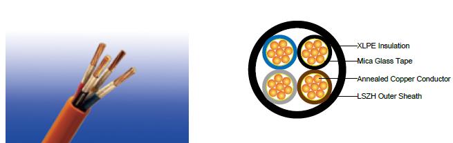
CABLE CONSTRUCTION
Conductor : Annealed copper conductor, stranded according to BS EN 60228 class 2.
Fire Barrier : Mica glass tape.
Insulation : Thermosetting insulation XLPE Type GP 8 according to BS 7655-1.3. HEPR Type GP 6 according to BS
7655-1.2 or crosslinked polyolefin material type EI 5 according to BS EN 50363-5 can be offered as option.
Inner Covering Option : The optional inner covering, where used, shall consist of an extruded layer of synthetic
polymeric material. It shall surround the single core and the laid-up two, three, four or five cores, giving the
assembly a practically circular shape.
Outer Sheath : Extruded layer of polymeric material LTS 4 according to BS 7655-6.1.
Outer Sheath Option : UV resistance, hydrocarbon resistance, oil resistance, anti-rodent and anti-termite
properties can be offered as option.
COLOUR CODE
Insulation Colour |
|
2-core |
Brown and blue. |
3-core |
Brown, black and grey. |
|
Alternatively, green-and-yellow, blue, brown. |
4-core |
Blue, brown black and grey. |
|
Alternatively, green-and-yellow, brown, black, grey. |
5-core |
Green-and-yellow, blue, brown black, grey. |
Sheath Colour |
Black; other colours can be offered upon request. |
PHYSICAL AND THERMAL PROPERTIES
Maximum temperature range during operation : 90°C
Maximum short circuit temperature (5 Seconds) : 250°C
Minimum bending radius
circular copper conductors OD≤25mm : 4 × Overall Diameter
circular copper conductors OD﹥25mm : 6 × Overall Diameter
shaped copper conductors : 8 × Overall Diameter
CONSTRUCTION PARAMETERS
Conductor |
FFX400 1mRZ1-R |
|||||
No. of Cores × Cross-sectional Area |
Conductor Class |
Nominal Insulation Thickness |
Nominal Inner Covering Thickness |
Nominal Sheath Thickness |
Approx. Overall Diameter |
Approx. Weight |
no.×mm² |
|
mm |
mm |
mm |
mm |
kg/km |
2 cores |
||||||
2×1.5a |
2 |
0.7 |
0.4 |
1.8 |
11.6 |
139 |
2×2.5a |
2 |
0.7 |
0.4 |
1.8 |
12.4 |
167 |
2×4a |
2 |
0.7 |
0.4 |
1.8 |
13.5 |
211 |
2×6a |
2 |
0.7 |
0.4 |
1.8 |
14.6 |
265 |
2×10a |
2 |
0.7 |
0.6 |
1.8 |
16.5 |
370 |
2×16a |
2 |
0.7 |
0.6 |
1.8 |
18.6 |
515 |
2×25a |
2 |
0.9 |
0.8 |
1.8 |
22.0 |
756 |
2×35a |
2 |
0.9 |
0.8 |
1.8 |
24.3 |
983 |
2×50a |
2 |
1.0 |
1.0 |
1.8 |
27.4 |
1281 |
2×70a |
2 |
1.1 |
1.0 |
1.8 |
31.4 |
1771 |
2×95a |
2 |
1.1 |
1.2 |
1.9 |
35.4 |
2379 |
2×120a |
2 |
1.2 |
1.2 |
2.0 |
39.2 |
2971 |
2×25b |
2 |
0.9 |
0.6 |
1.8 |
18.1 |
695 |
2×35b |
2 |
0.9 |
0.6 |
1.8 |
19.9 |
917 |
2×50b |
2 |
1.0 |
0.8 |
1.8 |
22.6 |
1209 |
2×70b |
2 |
1.1 |
0.8 |
1.8 |
25.5 |
1684 |
2×95b |
2 |
1.1 |
1.0 |
1.9 |
28.2 |
2273 |
2×120b |
2 |
1.2 |
1.0 |
2.0 |
31.0 |
2844 |
3 cores |
||||||
3×1.5a |
2 |
0.7 |
0.4 |
1.8 |
12.2 |
152 |
3×2.5a |
2 |
0.7 |
0.4 |
1.8 |
13.1 |
192 |
3×4a |
2 |
0.7 |
0.4 |
1.8 |
14.3 |
253 |
3×6a |
2 |
0.7 |
0.4 |
1.8 |
15.5 |
329 |
3×10a |
2 |
0.7 |
0.6 |
1.8 |
17.5 |
479 |
3×16a |
2 |
0.7 |
0.6 |
1.8 |
19.8 |
687 |
3×25a |
2 |
0.9 |
0.8 |
1.8 |
23.5 |
1033 |
3×35a |
2 |
0.9 |
0.8 |
1.8 |
26.0 |
1364 |
3×50a |
2 |
1.0 |
1.0 |
1.8 |
29.3 |
1798 |
3×70a |
2 |
1.1 |
1.2 |
1.9 |
33.8 |
2532 |
3×95a |
2 |
1.1 |
1.2 |
2.0 |
38.3 |
3421 |
3×120a |
2 |
1.2 |
1.2 |
2.1 |
42.4 |
4284 |
3×25b |
2 |
0.9 |
0.6 |
1.8 |
20.7 |
1001 |
3×35b |
2 |
0.9 |
0.8 |
1.8 |
23.3 |
1334 |
3×50b |
2 |
1.0 |
0.8 |
1.8 |
25.9 |
1757 |
3×70b |
2 |
1.1 |
1.0 |
1.9 |
29.8 |
2479 |
3×95b |
2 |
1.1 |
1.2 |
2.0 |
33.2 |
3351 |
3×120b |
2 |
1.2 |
1.2 |
2.1 |
36.0 |
4191 |
4 cores |
||||||
4×1.5a |
2 |
0.7 |
0.4 |
1.8 |
13.2 |
183 |
4×2.5a |
2 |
0.7 |
0.4 |
1.8 |
14.2 |
234 |
4×4a |
2 |
0.7 |
0.4 |
1.8 |
15.5 |
313 |
4×6a |
2 |
0.7 |
0.6 |
1.8 |
16.9 |
412 |
4×10a |
2 |
0.7 |
0.6 |
1.8 |
19.2 |
608 |
4×16a |
2 |
0.7 |
0.6 |
1.8 |
21.7 |
881 |
4×25a |
2 |
0.9 |
0.8 |
1.8 |
25.8 |
1335 |
4×35a |
2 |
0.9 |
1.0 |
1.8 |
28.6 |
1773 |
4×50a |
2 |
1.0 |
1.0 |
1.8 |
32.3 |
2344 |
4×70a |
2 |
1.1 |
1.2 |
2.0 |
37.5 |
3329 |
4×95a |
2 |
1.1 |
1.2 |
2.1 |
42.3 |
4505 |
4×120a |
2 |
1.2 |
1.2 |
2.3 |
47.1 |
5667 |
4×25b |
2 |
0.9 |
0.8 |
1.8 |
23.3 |
1305 |
4×35b |
2 |
0.9 |
0.8 |
1.8 |
25.9 |
1740 |
4×50b |
2 |
1.0 |
1.0 |
1.8 |
29.4 |
2307 |
4×70b |
2 |
1.1 |
1.2 |
2.0 |
33.5 |
3271 |
4×95b |
2 |
1.1 |
1.2 |
2.1 |
36.9 |
4424 |
4×120b |
2 |
1.2 |
1.2 |
2.3 |
40.9 |
5565 |
5 cores |
||||||
5×1.5a |
2 |
0.7 |
0.4 |
1.8 |
13.5 |
218 |
5×2.5a |
2 |
0.7 |
0.4 |
1.8 |
14.5 |
281 |
5×4a |
2 |
0.7 |
0.6 |
1.8 |
16.9 |
378 |
5×10a |
2 |
0.7 |
0.6 |
1.8 |
20.2 |
700 |
5×16a |
2 |
0.7 |
0.8 |
1.8 |
24.3 |
1042 |
5×25a |
2 |
0.9 |
1.0 |
1.8 |
27.3 |
1594 |
5×35a |
2 |
0.9 |
1.0 |
1.8 |
30.9 |
2132 |
5×50a |
2 |
1.0 |
1.2 |
1.9 |
34.6 |
2855 |
5×70a |
2 |
1.1 |
1.2 |
2.1 |
38.4 |
4055 |
5×95a |
2 |
1.1 |
1.4 |
2.2 |
43.7 |
5503 |
5×120a |
2 |
1.2 |
1.4 |
2.4 |
46.9 |
6916 |
a Circular or compacted circular stranded conductors (class 2).
b Shaped stranded conductor (class 2).
ELECTRICAL PROPERTIES
Conductor operating temperature : 90°C
Ambient temperature : 30°C
Current-Carrying Capacities (Amp) according to BS 7671:2008 table 4E2A
Conductor cross-sectional area |
Ref. Method A (enclosed in conduit in thermally insulating wall etc.) |
Ref. Method B (enclosed in conduit on a wall or in trunking etc.) |
Ref. Method C (clipped direct) |
Ref. Method E (in free air or on a perforated cable tray tec. horizontal or vertical) |
||||
1 two-core cable*, single-phase a.c. or d.c. |
1 three- or four-core cable*, three-phase a.c. |
1 two-core cable*, single-phase a.c. or d.c. |
1 three- or four-core cable*, three-phase a.c. |
1 two-core cable*, single-phase a.c. or d.c. |
1 three- or four-core cable*, three-phase a.c. |
1 two-core cable*, single-phase a.c. or d.c. |
1 three- or four-core cable*, three-phase a.c. |
|
mm² |
A |
A |
A |
A |
A |
A |
A |
A |
1.5 |
18.5 |
16.5 |
22 |
19.5 |
24 |
22 |
26 |
23 |
2.5 |
25 |
22 |
30 |
26 |
33 |
30 |
36 |
32 |
4 |
33 |
30 |
40 |
35 |
45 |
40 |
49 |
42 |
6 |
42 |
38 |
51 |
44 |
58 |
52 |
63 |
54 |
10 |
57 |
51 |
69 |
60 |
80 |
71 |
86 |
75 |
16 |
76 |
68 |
91 |
80 |
107 |
96 |
115 |
100 |
25 |
99 |
89 |
119 |
105 |
138 |
119 |
149 |
127 |
35 |
121 |
109 |
146 |
128 |
171 |
147 |
185 |
158 |
50 |
145 |
130 |
175 |
154 |
209 |
179 |
225 |
192 |
70 |
183 |
164 |
221 |
194 |
269 |
229 |
289 |
246 |
95 |
220 |
197 |
265 |
233 |
328 |
278 |
352 |
298 |
120 |
253 |
227 |
305 |
268 |
382 |
322 |
410 |
346 |
Note: *With or without a protective conductor.
Voltage Drop (Per Amp Per Meter) according to BS 7671:2008 table 4E2B
Conductor cross-sectional area |
Two-core cable, d.c. |
Two-core cable, single-phase a.c. |
Three- or four-core cable, three-phase a.c. |
||||
1 mm² |
2 mV/A/m |
3 mV/A/m |
4 mV/A/m |
||||
1.5 |
31 |
31 |
27 |
||||
2.5 |
19 |
19 |
16 |
||||
4 |
12 |
12 |
10 |
||||
6 |
7.9 |
7.9 |
6.8 |
||||
10 |
4.7 |
4.7 |
4.0 |
||||
16 |
2.9 |
2.9 |
2.5 |
||||
|
|
r |
x |
z |
r |
x |
z |
25 |
1.85 |
1.85 |
0.160 |
1.90 |
1.60 |
0.140 |
1.65 |
35 |
1.35 |
1.35 |
0.155 |
1.35 |
1.15 |
0.135 |
1.15 |
50 |
0.98 |
0.99 |
0.155 |
1.00 |
0.86 |
0.135 |
0.87 |
70 |
0.67 |
0.67 |
0.150 |
0.69 |
0.59 |
0.130 |
0.60 |
95 |
0.49 |
0.50 |
0.150 |
0.52 |
0.43 |
0.130 |
0.45 |
120 |
0.39 |
0.40 |
0.145 |
0.42 |
0.34 |
0.130 |
0.37 |