Applications :
- Cat6 Cable is a cable standard for Gigabit Ethernet and other network protocol, suitable for 10BaseT, 100BaseTx & 1000BaseT (Gigabit Ethernet) application. In addition, these cables are with copper wire braid armoured & flame retardant mud resistant outer sheath, providing additional mechanically protection still maintaining the flexibility of the cable.
Standards :
-
| IEC 60332-3-22 |
IEC 60754-1,2 |
| IEC 61034-1,2 |
NEK 606:2004 |
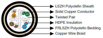
Construction :
- Conductors : 23AWG solid bare copper.
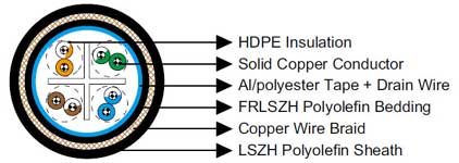
- Insulation : HDPE.
- Twinning : Two coloured insulated conductors twisted together to form a pair.
- Bedding : Flame retardant, low smoke and halogen-free polyolefin, coloured black.
- Armour : 0.2/0.3mm copper wire braid.
- Outer Sheath : Low smoke and halogen-free polyolefin.
Optional :
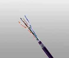
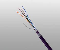
- Cat6 F/UTP : These cables have collective shielding of aluminium/Polyester tape with drain wire.
- Cat6 SF/UTP :These cables have double collective shieldings of aluminium/Polyester tape & copper wire braid with drain wire.
Electrical Characteristics :
-
| AWG |
|
24 |
| Nominal Conductor Diameter |
mm |
0.58 |
| Maximum DC Resistant@20℃ |
Ω/100m |
9.38 |
| Maximum DCR Unbalance |
% |
3 |
| Maximum Mutual Capacitance |
pF/m |
5.8 |
| Maximum Capacitance Unbalance |
pF/100m |
30 |
| Characteristic Impedance@1-100MHz |
Ω |
100+/-15 |
| Maximum Propagation Delay Skew |
ns/100m |
18 |
-
| FREQ MHz |
Maximum Attenuation dB/100m |
Minimum NEXT dB |
Minimum PSNEXT dB |
Minimum ELFEXT dB/100m |
Minimum PSELFEXT dB/100m |
Minimum RL dB |
| 0.772 |
1.8 |
76.0 |
74.0 |
70.0 |
67.0 |
— |
| 1 |
2.0 |
74.3 |
72.3 |
67.8 |
64.8 |
20.0 |
| 4 |
3.8 |
65.3 |
63.3 |
55.7 |
52.7 |
23.0 |
| 8 |
5.3 |
60.8 |
58.8 |
49.7 |
46.7 |
24.5 |
| 10 |
6.0 |
59.3 |
57.3 |
47.8 |
44.8 |
25.0 |
| 16 |
7.6 |
56.3 |
54.3 |
43.7 |
40.7 |
25.0 |
| 20 |
8.5 |
54.8 |
52.8 |
41.7 |
38.7 |
25.0 |
| 25 |
9.5 |
53.3 |
51.3 |
39.8 |
36.8 |
24.3 |
| 31.25 |
10.7 |
51.9 |
49.9 |
37.9 |
34.9 |
23.6 |
| 62.5 |
15.4 |
47.4 |
45.4 |
31.8 |
28.8 |
21.5 |
| 100 |
19.8 |
44.3 |
42.3 |
27.8 |
24.8 |
20.1 |
| 155 |
25.2 |
41.5 |
39.5 |
23.9 |
20.9 |
18.8 |
| 200 |
29.0 |
39.8 |
37.8 |
21.7 |
18.7 |
18.0 |
| 250 |
32.8 |
38.3 |
36.3 |
19.8 |
16.8 |
17.3 |
Mechanical and Thermal Properties :
- Bending Radius : 8×OD (during installation); 4×OD (fixed installed).
- Temperature Range : -30℃ ~ +75℃.
Dimensions and Weight :
Construction No. of elements×No. of cores in element×Conductor diameter
(mm²) |
Nominal Insulation Thickness
mm |
Nominal Sheath Thickness
mm |
Nominal Overall Diameter
mm |
Nominal Weight
kg/km |
| 4×2×0.58 |
0.2 |
1.2 |
11.5 |
214 |
|