


| BS 5308 Cables | |||
 PAS 5308 Cables
PAS 5308 Part 2 / Type 2 (Armoured Cables)
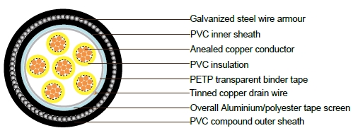
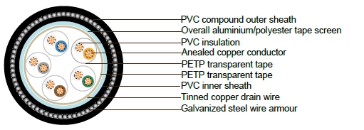
PAS 5308 Cable Part 2 Type 2 PVC-OS-SWA-PVC
Applications
PAS 5308 cables are designed to connect electrical instrumentation and communication systems in and around
process plants and similar applications. Generally used to transmit analogue or digital signals in measurement
and process control where chemicals may be present. PAS 5308 armoured version are well adapted to
underground use in industrial applications where chemical and mechanical protections are needed (refinery
areas, chemical plant...).
Construction
Conductor
Annealed copper, sizes: 0.5mm² and 0.75mm² mulitistranded(Class 5), 1.5mm² and 2.5mm² multistranded(Class
2) to BS EN 60228
Insulation
PVC to BS EN 50290-2-21:2002, grade TI51
Pairing
Two insulated conductors uniformly twisted together with a lay not exceeding 100mm, Two-pair cables without
individual pair screens (quads) shall have four cores laid in quad formation round a central dummy
Colour code
Multicore cables: up to 40 cores yellow with black numbers, 41 - 80 cores black with yellow numbers. Multipair
cables:See technical information
Binder tape
Non-hygroscopic binder tape of minimum thickness 0.023 mm
Collective screen
Aluminium/polyester tape is applied over the laid up pairs metallic side down in contact with tinned copper drain
wire, 0.5mm²
Inner Sheath
Extruded sheath of a PVC compound conforming to BS EN 50290-2-22:2002, grade TM51
Amour
Galvanized steel wire armour
Outer sheath
Extruded sheath of a PVC compound conforming to BS EN 50290-2-22:2002, grade TM51
Sheath colour
Generally black
Electrical Properties
| Temperature range | above 0˚C( fixed installation) |
|---|---|
| -15˚C to +65˚C(during operation ) |
| Conductor Area Size | mm² | 0.5 | 0.5 | 1.0 | 1.5 | 2.5 | |
|---|---|---|---|---|---|---|---|
| Conductor Stranding | No. x mm | 1 x 0.8 | 16 x 0.2 | 1 x 1.13 | 7 x 0.53 | 7 x 0.67 | |
| Conductor resistance max | ohm/km | 36.8 | 39.7 | 18.4 | 12.3 | 7.6 | |
| Insulation resistance min | Individual conductor | Gohm/km | 5 | 5 | 5 | 5 | 5 |
| individual screen | Mohm/km | 1 | 1 | 1 | 1 | ||
| Capacitance unbalance at 1kHz(pair to pair screen) | pF/250m | 250 | |||||
| Max. Mutual Capacitance @ 1kHz for Non OS or OS cables (except one-pair and two-pairs) | pF/m | 75 | 75 | 75 | 85 | 105 | |
| Max. Mutual Capacitance @ 1kHz IS/OS cables (include 1 pairand 2 pair) | pF/m | 115 | 115 | 115 | 120 | 140 | |
| Max. L/R Ratio for adjacentcores(Inductance/Resistance) | μH/ohm | 25 | 25 | 25 | 40 | 60 | |
| Test voltage | V | 2000 | 2000 | 2000 | 2000 | 2000 | |
| Rated voltage | V | 300/500 | 300/500 | 300/500 | 300/500 | 300/500 | |
Parameter
Multicore
| Number of Cores | Nominal Thickness of Insulation | Nominal Thickness of bedding | Nominal Diameter over Bedding | Nominal Thickness of Armour | Nominal Diameter over Armour | Nominal Thickness of Sheath | Nominal Diameter of Cable |
|---|---|---|---|---|---|---|---|
| mm | mm² | mm | mm | mm | mm | ||
| stranded conductor 0.5 mm² (16/0.20mm) | |||||||
| 2 | 0.6 | 0.8 | 6 | 0.9 | 7.8 | 1.3 | 10.4 |
| 3 | 0.6 | 0.8 | 6.3 | 0.9 | 8.1 | 1.3 | 10.7 |
| 4 | 0.6 | 0.8 | 6.9 | 0.9 | 8.7 | 1.3 | 11.3 |
| 6 | 0.6 | 0.8 | 8.1 | 0.9 | 9.9 | 1.4 | 12.7 |
| 10 | 0.6 | 0.9 | 10.4 | 1.25 | 12.9 | 1.5 | 15.9 |
| 20 | 0.6 | 1 | 13.5 | 1.25 | 16 | 1.5 | 19 |
| 40 | 0.6 | 1.2 | 18.2 | 1.6 | 21.4 | 1.7 | 24.8 |
| 80 | 0.6 | 1.4 | 25.1 | 2 | 29.1 | 1.9 | 32.9 |
| stranded conductor 0.75 mm² (24/0.20mm) | |||||||
| 2 | 0.6 | 1.3 | 10.8 | 0.8 | 6.4 | 0.9 | 8.2 |
| 3 | 0.6 | 1.3 | 11.2 | 0.8 | 6.8 | 0.9 | 8.6 |
| 4 | 0.6 | 1.4 | 12 | 0.8 | 7.4 | 0.9 | 9.2 |
| 6 | 0.6 | 1.4 | 13.5 | 0.9 | 8.9 | 0.9 | 10.7 |
| 10 | 0.6 | 1.5 | 17 | 1 | 11.5 | 1.25 | 14 |
| 20 | 0.6 | 1.6 | 20.5 | 1.1 | 14.8 | 1.25 | 17.3 |
| 40 | 0.6 | 1.7 | 26.5 | 1.3 | 19.9 | 1.6 | 23.1 |
| 80 | 0.6 | 2 | 35.5 | 1.5 | 27.5 | 2 | 31.5 |
| stranded conductor 1.5 mm² (7/0.53mm) | |||||||
| 2 | 0.6 | 0.8 | 7.3 | 0.9 | 9.1 | 1.4 | 11.9 |
| 3 | 0.6 | 0.8 | 7.7 | 0.9 | 9.5 | 1.4 | 12.3 |
| 4 | 0.6 | 0.9 | 8.7 | 0.9 | 10.5 | 1.4 | 13.3 |
| 6 | 0.6 | 0.9 | 10.3 | 1.25 | 12.8 | 1.5 | 15.8 |
| 10 | 0.6 | 1 | 13.3 | 1.25 | 15.8 | 1.5 | 18.8 |
| 20 | 0.6 | 1.2 | 17.4 | 1.6 | 20.6 | 1.7 | 24 |
| 40 | 0.6 | 1.4 | 23.4 | 1.6 | 26.6 | 1.8 | 30.2 |
| 80 | 0.6 | 1.7 | 32.6 | 2 | 36.6 | 2.1 | 40.8 |
| stranded conductor 2.5 mm² (7/0.67mm) | |||||||
| 2 | 0.6 | 0.8 | 8.1 | 0.9 | 9.9 | 1.4 | 12.7 |
| 3 | 0.6 | 0.9 | 8.8 | 0.9 | 10.6 | 1.4 | 13.4 |
| 4 | 0.6 | 0.9 | 9.7 | 0.9 | 11.5 | 1.4 | 14.3 |
| 6 | 0.6 | 1 | 11.7 | 1.25 | 14.2 | 1.5 | 17.2 |
| 10 | 0.6 | 1.1 | 15.1 | 1.6 | 18.3 | 1.6 | 21.5 |
| 20 | 0.6 | 1.3 | 19.9 | 1.6 | 23.1 | 1.7 | 26.5 |
| 40 | 0.6 | 1.5 | 26.7 | 2 | 30.7 | 2 | 34.7 |
| 80 | 0.6 | 1.9 | 37.3 | 2.5 | 42.3 | 2.3 | 46.9 |
Multipair
| Number of Cores | Number and Diameter of Wires | Nominal Conductor Cross-Sectional Area | Nominal Thickness of Insulation | Nominal Thickness of Sheath | Nominal Diameter of Cable |
|---|---|---|---|---|---|
| no./mm | mm² | mm | mm | mm | |
| stranded conductor 0.5 mm² (16/0.20mm) | |||||
| 1 | 16/0.2 | 0.5 | 0.6 | 0.8 | 6 |
| 2 | 16/0.2 | 0.5 | 0.6 | 0.8 | 6.9 |
| 5 | 16/0.2 | 0.5 | 0.6 | 1 | 11.9 |
| 10 | 16/0.2 | 0.5 | 0.6 | 1.1 | 16.4 |
| 15 | 16/0.2 | 0.5 | 0.6 | 1.2 | 19 |
| 20 | 16/0.2 | 0.5 | 0.6 | 1.3 | 21.5 |
| 30 | 16/0.2 | 0.5 | 0.6 | 1.5 | 25.7 |
| 50 | 16/0.2 | 0.5 | 0.6 | 1.7 | 32.9 |
| stranded conductor 0.75 mm² (24/0.20mm) | |||||
| 1 | 24/0.2 | 0.75 | 0.6 | 0.8 | 6.4 |
| 2 | 24/0.2 | 0.75 | 0.6 | 0.8 | 7.4 |
| 5 | 24/0.2 | 0.75 | 0.6 | 1 | 12.8 |
| 10 | 24/0.2 | 0.75 | 0.6 | 1.2 | 17.9 |
| 15 | 24/0.2 | 0.75 | 0.6 | 1.3 | 20.9 |
| 20 | 24/0.2 | 0.75 | 0.6 | 1.4 | 23.6 |
| 30 | 24/0.2 | 0.75 | 0.6 | 1.5 | 27.9 |
| 50 | 24/0.2 | 0.75 | 0.6 | 1.8 | 35.9 |
| stranded conductor 1.5 mm² (7/0.53mm) | |||||
| 1 | 7/0.53 | 1.5 | 0.6 | 0.8 | 7.3 |
| 2 | 7/0.53 | 1.5 | 0.6 | 0.9 | 8.7 |
| 5 | 7/0.53 | 1.5 | 0.6 | 1.1 | 15.1 |
| 10 | 7/0.53 | 1.5 | 0.6 | 1.3 | 21.1 |
| 15 | 7/0.53 | 1.5 | 0.6 | 1.4 | 24.6 |
| 20 | 7/0.53 | 1.5 | 0.6 | 1.5 | 27.7 |
| 30 | 7/0.53 | 1.5 | 0.6 | 1.7 | 33 |
| 50 | 7/0.53 | 1.5 | 0.6 | 2.1 | 42.7 |
| stranded conductor 2.5 mm² (7/0.67mm) | |||||
| 1 | 7/0.67 | 2.5 | 0.6 | 0.8 | 8.1 |
| 2 | 7/0.67 | 2.5 | 0.6 | 0.9 | 9.7 |
| 5 | 7/0.67 | 2.5 | 0.6 | 1.2 | 17.2 |
| 10 | 7/0.67 | 2.5 | 0.6 | 1.4 | 24.1 |
| 15 | 7/0.67 | 2.5 | 0.6 | 1.6 | 28.2 |
| 20 | 7/0.67 | 2.5 | 0.6 | 1.7 | 31.8 |
| 30 | 7/0.67 | 2.5 | 0.6 | 1.9 | 37.9 |
| 50 | 7/0.67 | 2.5 | 0.6 | 2.3 | 48.9 |